Propeller Shaft and Constant Velocity Universal Joint Used Therein
a technology of propeller shaft and universal joint, which is applied in the direction of mechanical equipment, couplings, transportation and packaging, etc., can solve the problems of increasing the production cost of the vehicle, affecting the production efficiency of the vehicle, and affecting the fit of the boot to the desired position of the propeller sha
- Summary
- Abstract
- Description
- Claims
- Application Information
AI Technical Summary
Benefits of technology
Problems solved by technology
Method used
Image
Examples
first embodiment
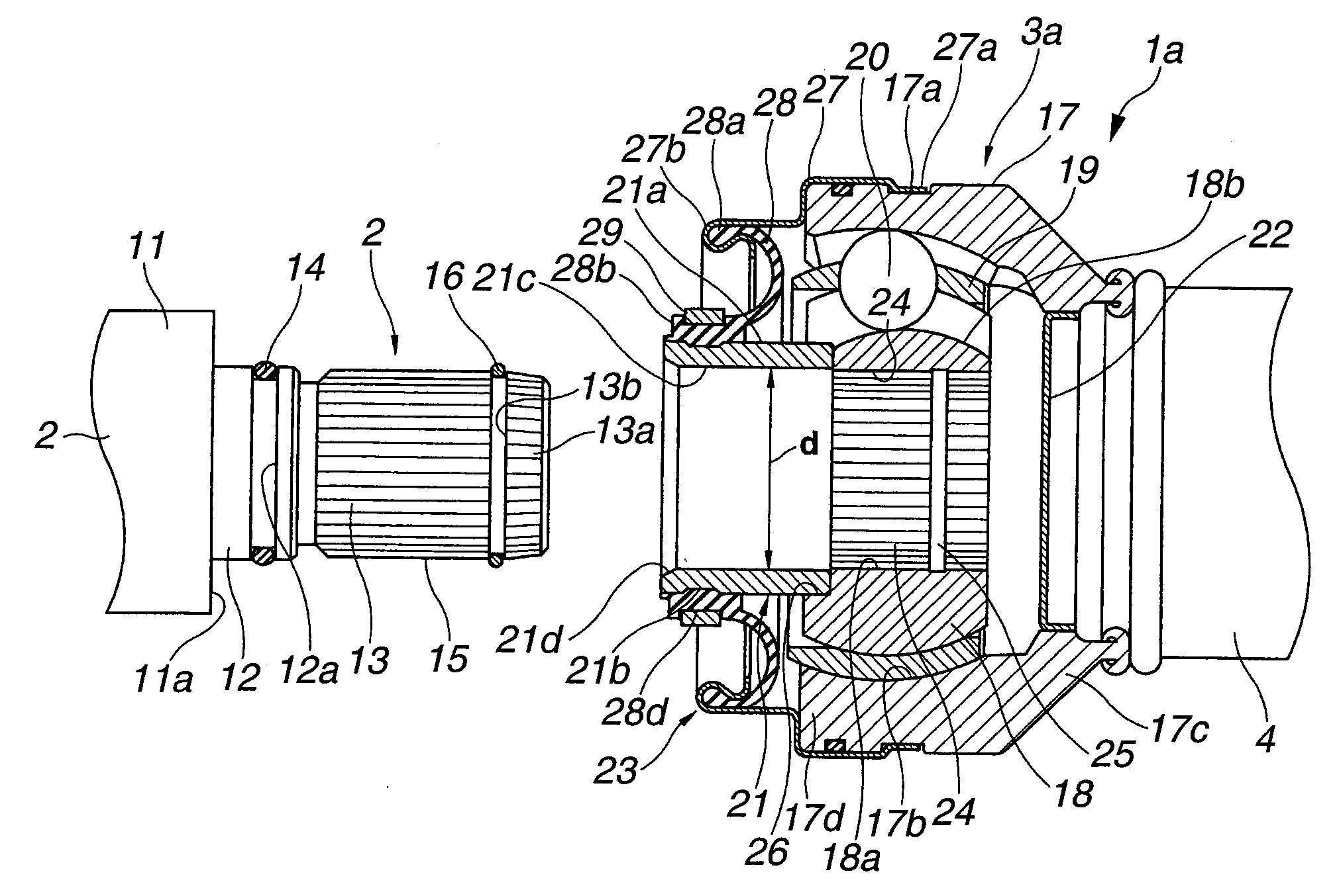
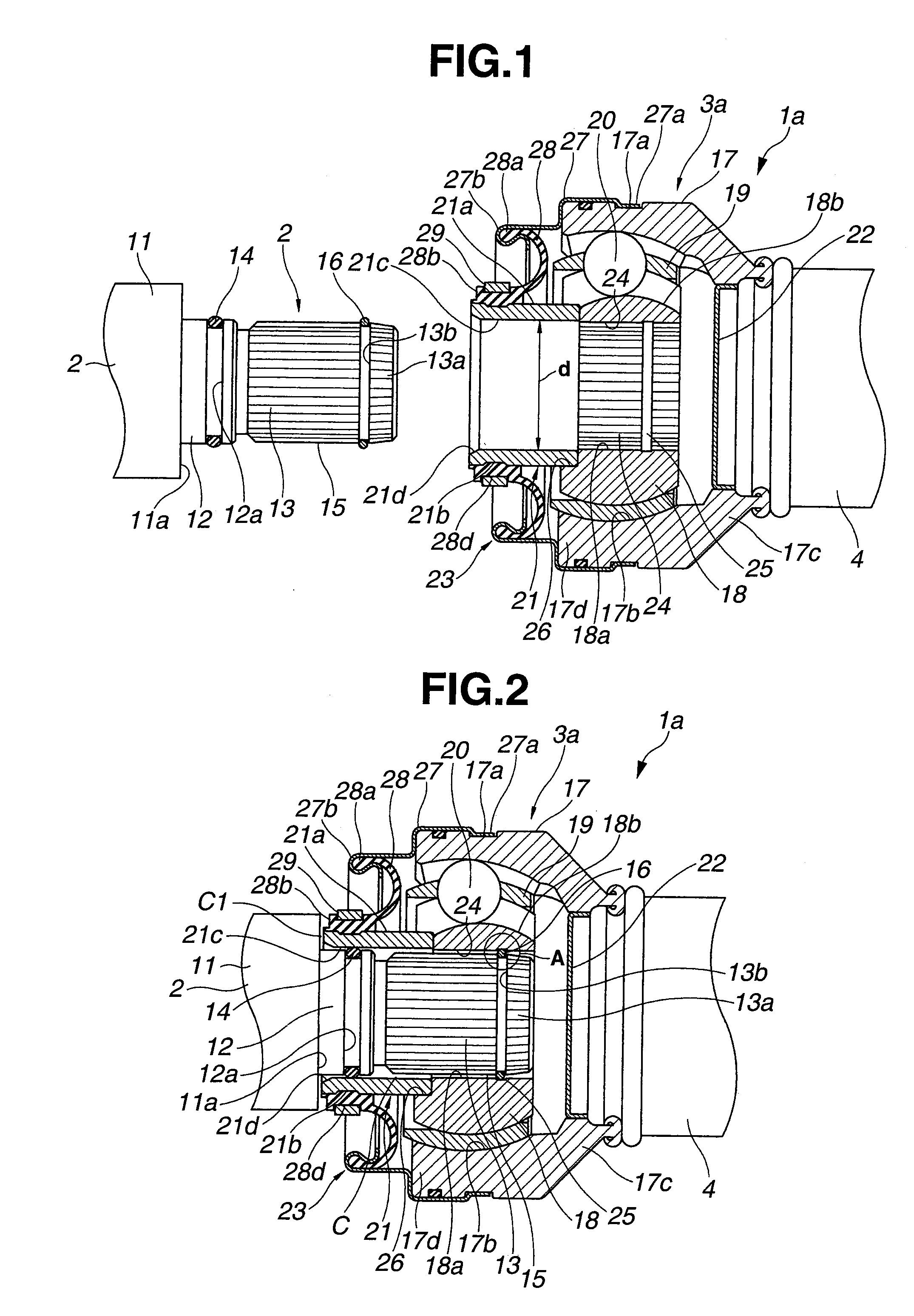
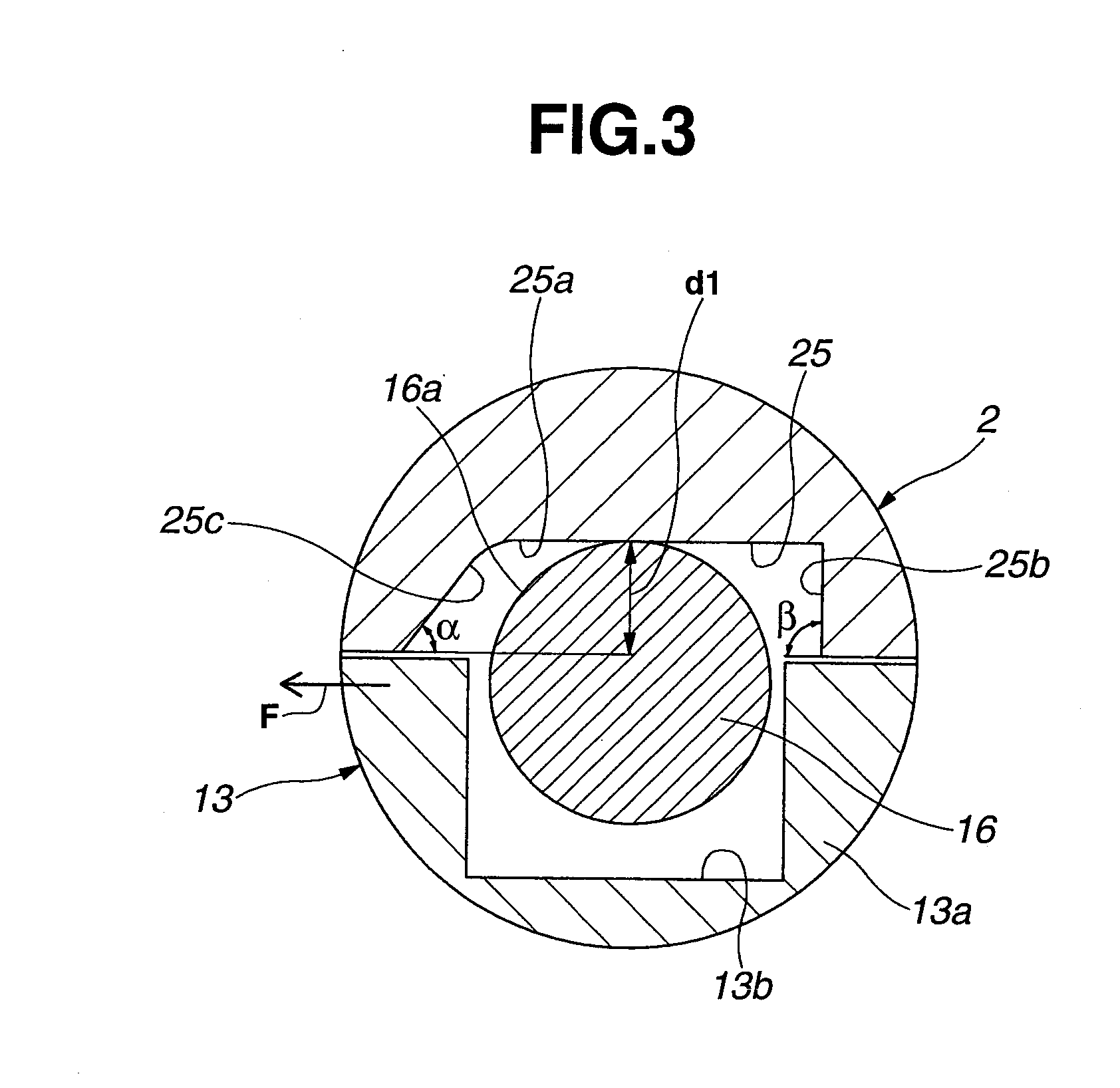
[0025]Referring to FIGS. 1 to 4, there is shown a propeller shaft is which is the present invention.
[0026]As is seen from FIG. 4, propeller shaft 1a comprises an input shaft 2 of steel that is adapted to connect to an output shaft of a transmission (not shown) mounted on a motor vehicle, a drive shaft 4 of aluminum alloy that is connected to input shaft 2 through a first constant velocity universal joint 3a, a driven shaft 6 of aluminum alloy that is connected to drive shaft 4 through a second constant velocity universal joint 5 and an output shaft 8 of steel that is connected to driven shaft 6 through a third constant velocity universal joint 7 and connected to an input shaft of a differential gear (not shown). As shown, when propeller shaft is practically used, a center bearing 9 holding an axially given portion of propeller shaft is supported by a vehicle body “VB” through a bracket 10. In the illustrated embodiment, center bearing 9 holds a right end of drive shaft 4 at a positi...
second embodiment
[0070]Referring to FIG. 5, there is shown a front assembly of a propeller shaft 1b which is the present invention.
[0071]Since this second embodiment is similar to the above-mentioned first embodiment, only parts or portions that are different from those of the first embodiment will be described in the following.
[0072]As is seen from FIG. 5, in this second embodiment, in addition to annular groove 12a, another annular groove (viz., second annular groove) 12b is provided by medium diameter intermediate portion 12 of input shaft 2. A second seal ring 29 is tightly held by second annular groove 12b. Like the seal ring 14, second seal ring 29 is pressed against the smoothed cylindrical inner surface of sleeve member 21.
[0073]Because of usage of two seal rings 14 and 19, much effective sealing against muddy water, dusts or the like is obtained in this embodiment. Furthermore, due to provision of such two seal rings 14 and 19, undesired leakage of the grease from the interior of outer cyli...
third embodiment
[0074]Referring to FIG. 6, there is shown a front assembly of a propeller shaft 1c which is the present invention.
[0075]In this third embodiment, the axial length of medium diameter intermediate portion 12 of input shaft 2 is small as compared with those of the above-mentioned first and second embodiments.
[0076]Furthermore, in this third embodiment, a seal ring 31 is tightly received in an annular groove 30 that is formed on the smoothed inner cylindrical wall of sleeve member 21. In use, seal ring 31 is pressed against the cylindrical outer surface of medium diameter intermediate portion 12 of input shaft 2.
PUM
 Abstract
Description
Claims
Application Information
 - R&D
- Intellectual Property
- Life Sciences
- Materials
- Tech Scout
- Unparalleled Data Quality
- Higher Quality Content
- 60% Fewer Hallucinations
Browse by: Latest US Patents, China's latest patents, Technical Efficacy Thesaurus, Application Domain, Technology Topic, Popular Technical Reports.
© 2025 PatSnap. All rights reserved.Legal|Privacy policy|Modern Slavery Act Transparency Statement|Sitemap|About US| Contact US: help@patsnap.com


