
Containerized mobile gas turbine filter test facility

a gas turbine and filter technology, applied in the direction of filtration separation, instruments, separation processes, etc., can solve the problems of difficult to determine the effectiveness/efficiency of the filter elements in the gas turbine inlet system, the cost and/or inefficiency of shutting down the turbine inlet system to remove, replace,

Inactive Publication Date: 2013-10-03
BHA ALTAIR
View PDF9 Cites 7 Cited by
  • Summary
  • Abstract
  • Description
  • Claims
  • Application Information

AI Technical Summary

Benefits of technology

The present invention provides a portable filter testing assembly for testing filter elements. The testing assembly includes a first modular component and a second modular component. The first modular component has a fluid flow inlet and a self-contained rectangular cuboid enclosure that supports filter elements and has fluid flow openings. The second modular component has fluid flow drawing means for drawing fluid flow through the filter elements of the first modular component. The testing assembly also includes a method of using transportable modular components for testing filter elements by aligning and coupling the fluid flow openings of the modular components and drawing fluid flow from the first component to the second component. The invention provides a portable, efficient, and effective solution for testing filter elements.

Problems solved by technology

Incorporating untested or developmental filter elements (“test filter elements”) in a gas turbine inlet system may be problematic to the inlet system if the test filter elements do not perform up to expectations by not filtering at a certain minimum efficiency.
Moreover, determining the effectiveness / efficiency of the filter elements in the gas turbine inlet system may be difficult because the results of the test filter elements can be masked with the results of non-test filter elements.
Even further, it can be costly and / or inefficient to shut down the turbine inlet system to remove, replace, and test the test filter elements.

Method used


Image

  • Containerized mobile gas turbine filter test facility
  • Containerized mobile gas turbine filter test facility
  • Containerized mobile gas turbine filter test facility

Examples


Embodiment Construction

[0013]Example embodiments that incorporate one or more aspects of the invention are described and illustrated in the drawings. These illustrated examples are not intended to be a limitation on the invention. For example, one or more aspects of the invention can be utilized in other embodiments and even other types of devices. Moreover, certain terminology is used herein for convenience only and is not to be taken as a limitation on the invention. Still further, in the drawings, the same reference numerals are employed for designating the same elements.

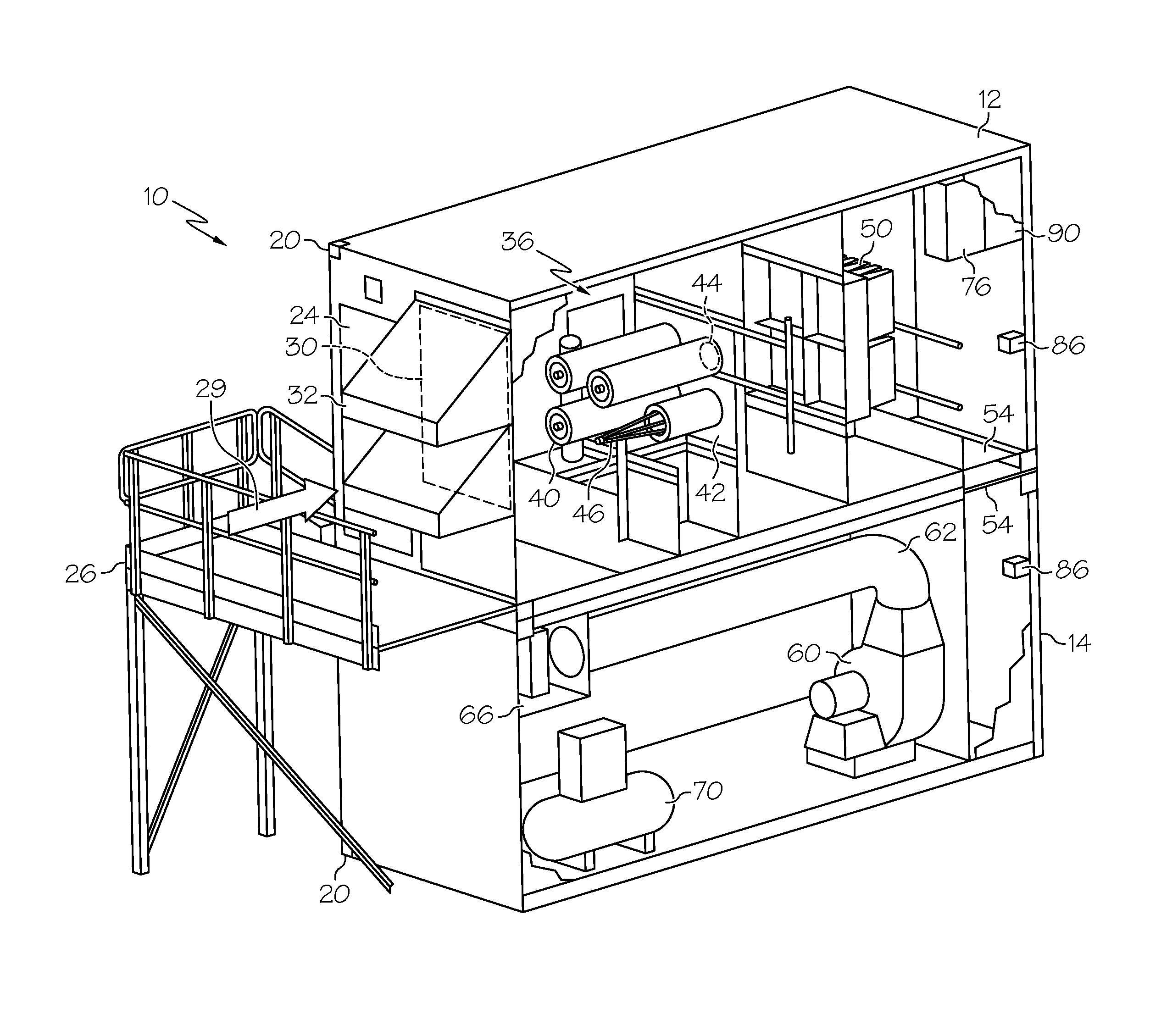
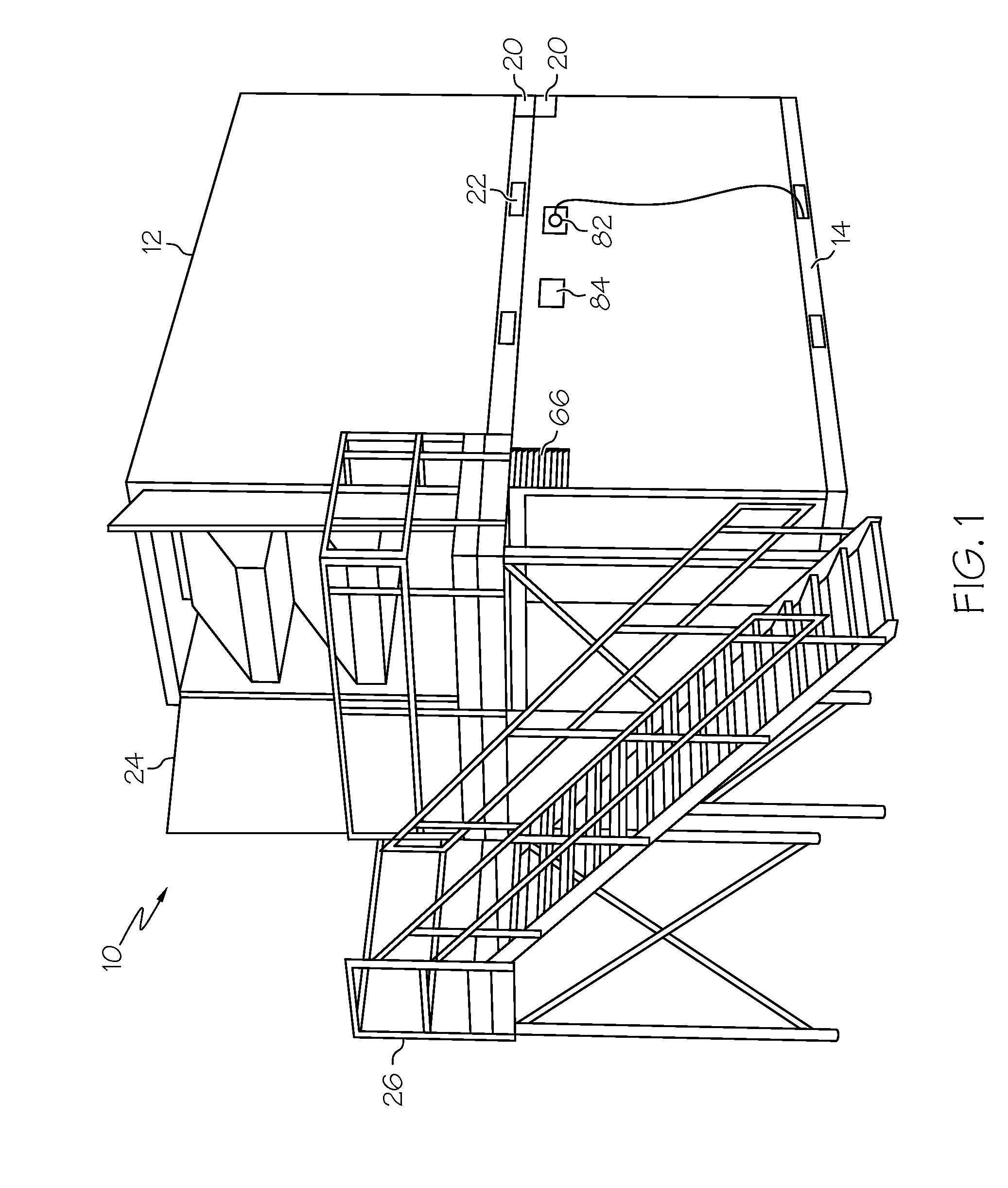
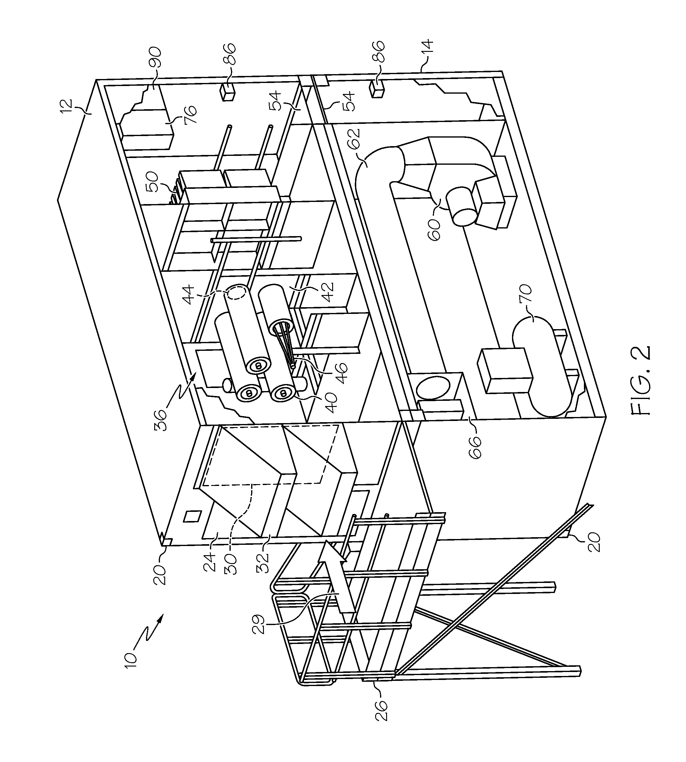
[0014]FIG. 1 illustrates a perspective view of an example portable filter testing assembly 10 in accordance with one aspect of the subject invention. The portable filter testing assembly 10 can include a first modular component 12 and a second modular component 14 arranged in a vertically stacked orientation. In brief synopsis, the first modular component 12 includes one or more filter elements (shown in FIG. 2) for test-filtering flui...


PUM

PropertyMeasurementUnit
Temperatureaaaaaaaaaa
Flow rateaaaaaaaaaa
Speedaaaaaaaaaa

Abstract

A portable filter testing assembly for testing filter elements is provided. The portable filter testing assembly includes a first modular component including filter elements disposed within an interior and a fluid flow inlet. The testing assembly further includes a second modular component in fluid communication with the first modular component and includes fluid flow drawing means for drawing fluid flow through the filter elements of the first modular component such that the fluid flow is filtered by the filter elements. Each of the first modular component and second modular component includes an external structure of a modular International Organization for Standardization (ISO) shipping container. A kit of plural modular components for testing filter elements is provided. A method of using ISO modular components for testing filter elements is also provided.

Description

BACKGROUND OF THE INVENTION[0001]1. Field of the Invention[0002]The invention relates to a filter assembly and, more particularly, to a portable filter testing assembly for testing filter elements to be used in a gas turbine inlet.[0003]2. Discussion of Prior Art[0004]Filter elements are typically used in gas turbine inlet systems for filtering entering air flow. Incorporating untested or developmental filter elements (“test filter elements”) in a gas turbine inlet system may be problematic to the inlet system if the test filter elements do not perform up to expectations by not filtering at a certain minimum efficiency. Moreover, determining the effectiveness / efficiency of the filter elements in the gas turbine inlet system may be difficult because the results of the test filter elements can be masked with the results of non-test filter elements. Even further, it can be costly and / or inefficient to shut down the turbine inlet system to remove, replace, and test the test filter eleme...

Claims


Application Information

Patent Timeline
IPC IPC(8): G01N15/08
CPCF05D2260/83F02C7/05B01D35/30B01D35/301B01D35/303B01D46/00B01D46/0002B01D46/0013
Inventor SMITH, PETER JOHN DUNCANHINER, STEPHEN DAVIDBANKS, STEPHEN FRANCIS
Owner BHA ALTAIR
Learn More