Lubricant reservoir refilling system with shut-off
Inactive Publication Date: 2013-10-03
LINCOLN INDUSTRIES CORP
View PDF4 Cites 29 Cited by
Summary
Abstract
Description
Claims
Application Information
AI Technical Summary
This helps you quickly interpret patents by identifying the three key elements:
Problems solved by technology
Method used
Benefits of technology
[0003]In one aspect, the present invention includes a lubricant reservoir system, comprising a reservoir for containing lubricant. The reservoir includes a top, a bottom, a peripheral wall, and an inlet for delivering lubricant to the reservoir from a supply. The system also includes a follower in the reservoir slidingly and sealingly engaging the peripheral wall of the reservoir, the follower moving up and down in
Problems solved by technology
In other systems, the user is notified by a light on the reservoir, which can be difficult to see because of the distance
Method used
Image
Click on the blue label to locate the original text in one second.
Reading with bidirectional positioning of images and text.
Examples
Embodiment Construction
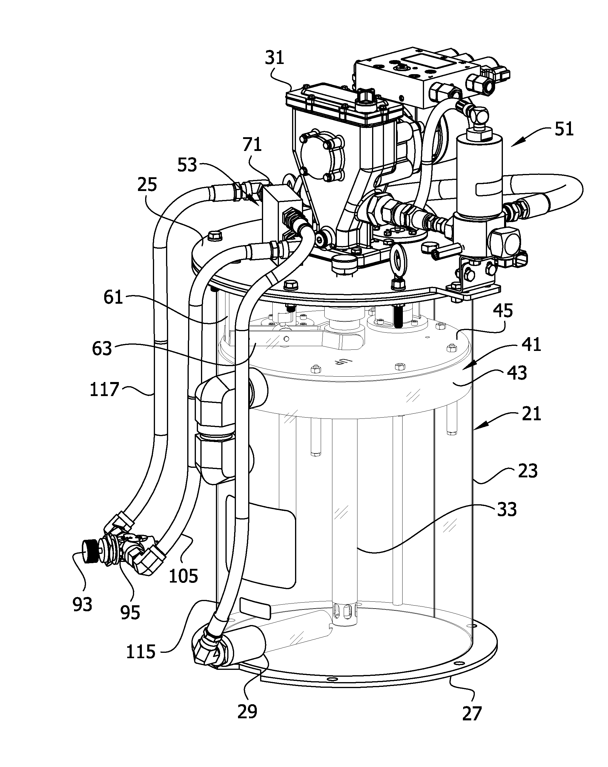
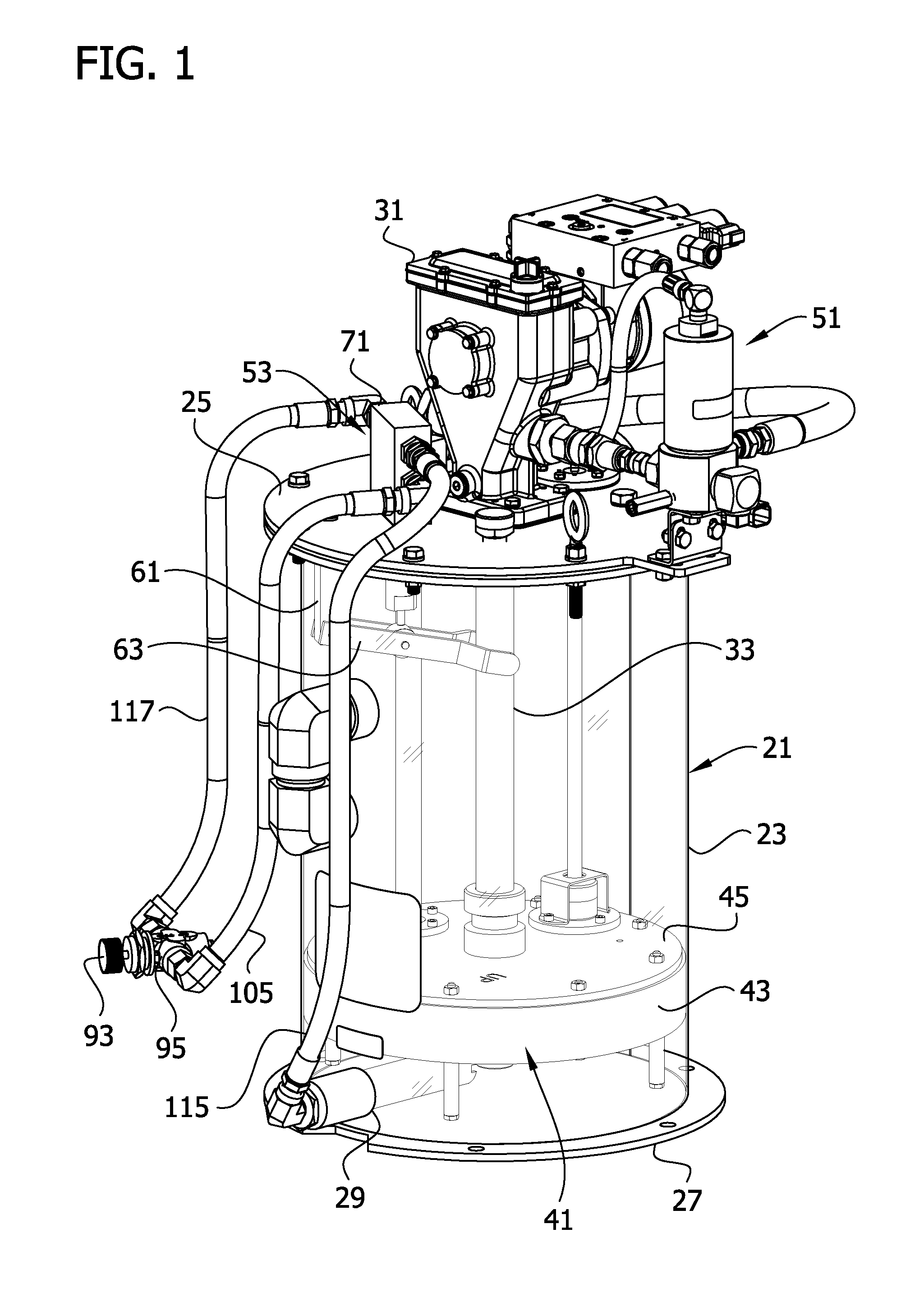
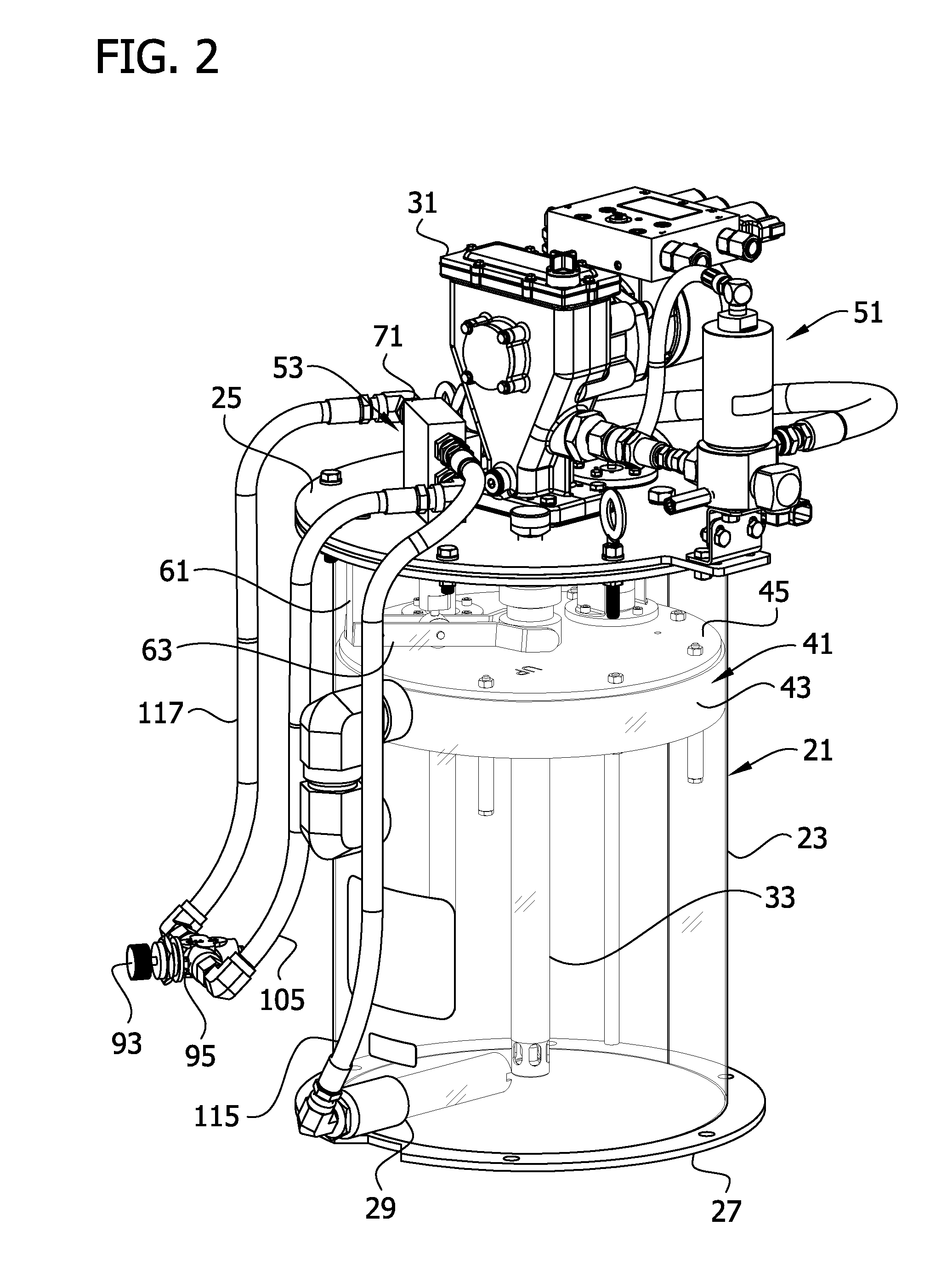
[0014]Referring to FIGS. 1 and 2, a reservoir or drum of the present invention, constructed particularly for retaining lubricant, especially grease, is designated in its entirety by the reference number 21. The reservoir 21 comprises a generally circular peripheral wall 23 closed at an upper end by a removable top plate or lid 25 and closed at a lower end by a bottom plate 27. An inlet 29 is provided in the peripheral wall 23 near the bottom 27 of the reservoir 21 for refilling the reservoir. The reservoir 21 can be made of metal, such as steel, or any other suitable material known in the art. The reservoir 21 can be any size, and in one embodiment has a sixteen inch diameter. A pump 31 including a lance structure 33 is mounted on the top 25 of the reservoir 21 so the lance structure extends down into the reservoir toward the bottom plate 27 through a hole (not shown) in the top. The pump 31 can be any pump suitable for pumping lubricant, especially grease. For example, in one embod...
PUM
Abstract
A lubricant reservoir system. The system includes a reservoir for containing lubricant. The reservoir has a top, a bottom, a peripheral wall, and an inlet for delivering lubricant to the reservoir from a supply. The system also includes a follower in the reservoir slidingly and sealingly engaging the peripheral wall of the reservoir, the follower moving up and down in the reservoir in response to a changing level of lubricant in the reservoir. The lubricant reservoir system has a shut-off valve in fluid communication with the inlet for selectively preventing lubricant flow through the inlet. The valve is operatively connected to the follower for closing the valve and preventing lubricant flow through the inlet when lubricant in the reservoir reaches a predetermined level.
Description
FIELD OF THE INVENTION[0001]This invention relates to lubricant reservoirs, and more particularly to a system for refilling a lubricant reservoir from a supply of lubricant.BACKGROUND OF THE INVENTION[0002]Pumps such as those shown in the following U.S. Pat. Nos. 2,187,684; 2,636,441; 2,787,225; 3,469,532; 3,502,029; 3,945,772; 4,487,340; 4,762,474; and 6,102,676, operate to pump lubricant from a reservoir. When the amount of lubricant in the reservoir is depleted, the reservoir must be refilled with lubricant. The reservoir is typically refilled via hoses attached to a supply of lubricant. Often, the supply is located some distance from the reservoir. For example, the reservoir may be located in a building and the supply may be located in a truck outside the building. To avoid overfilling the reservoir, the user must stop pumping lubricant from the supply when the amount of lubricant in the reservoir reaches a certain level. Currently, the user is notified that the reservoir is fil...
Claims
Application Information
Patent Timeline
Application Date:The date an application was filed.
Publication Date:The date a patent or application was officially published.
First Publication Date:The earliest publication date of a patent with the same application number.
Issue Date:Publication date of the patent grant document.
PCT Entry Date:The Entry date of PCT National Phase.
Estimated Expiry Date:The statutory expiry date of a patent right according to the Patent Law, and it is the longest term of protection that the patent right can achieve without the termination of the patent right due to other reasons(Term extension factor has been taken into account ).
Invalid Date:Actual expiry date is based on effective date or publication date of legal transaction data of invalid patent.