Detection for four pair powered devices

a technology of power-powered devices and detection devices, applied in the direction of data switching details, electrical equipment, ac network circuit arrangements, etc., to achieve the effect of high impedance results

Active Publication Date: 2013-10-03
MICROSEMI CORP ANALOG MIXED SIGNAL GRP LTD
View PDF1 Cites 32 Cited by
  • Summary
  • Abstract
  • Description
  • Claims
  • Application Information

AI Technical Summary

Benefits of technology

[0018]Accordingly, it is a principal object of the present invention to overcome the disadvantages of prior art in powering remote devices. This is provided in the present invention by a method of detection in which two PSEs associated with a single PD initiate a simultaneous detection phase prior to performing independent detection. In the event that the simultaneous detection is indicative that no PD is connected on either path, i.e. both PSEs return a high impedance result, powering of the PD is not performed by either of the PSEs. In one embodiment, alternate detection is not performed in the event that the simultaneous detection is indicative that no PD is connected on either path.

Problems solved by technology

Such a condition is problematic as it leads to unexpected results.

Method used


Image

  • Detection for four pair powered devices
  • Detection for four pair powered devices
  • Detection for four pair powered devices

Examples


Embodiment Construction

[0030]Before explaining at least one embodiment of the invention in detail, it is to be understood that the invention is not limited in its application to the details of construction and the arrangement of the components set forth in the following description or illustrated in the drawings. The invention is applicable to other embodiments or of being practiced or carried out in various ways. Also, it is to be understood that the phraseology and terminology employed herein is for the purpose of description and should not be regarded as limiting.

[0031]The invention is being described as an Ethernet based network, with a powered device being connected thereto. It is to be understood that the powered device is preferably an IEEE 802.3 compliant device preferably employing a 10Base-T, 100Base-T or 1000Base-T connection.

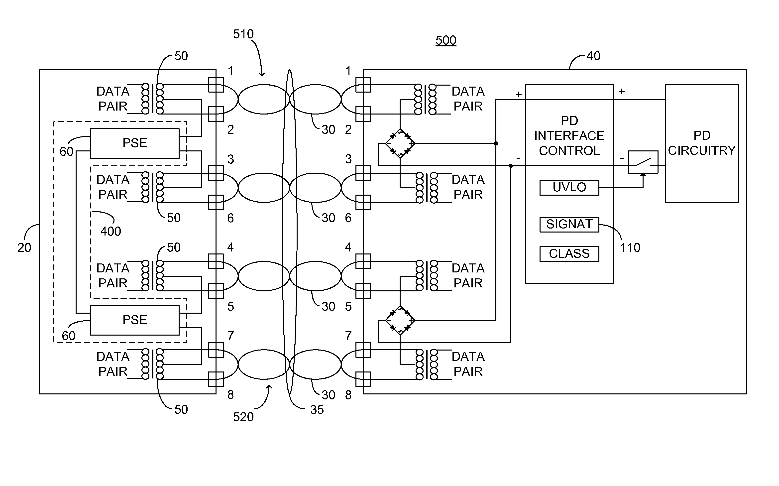
[0032]FIG. 2 illustrates a high level block diagram of an exemplary twin PSE 400 comprising a first PSE 60 and a second PSE 60. Each PSE 60 comprises: a control circuitry ...


PUM


Abstract

A twin power sourcing equipment constituted of: a first power sourcing equipment; and a second power sourcing equipment arranged for connection to a powered device over respective power paths; the first and second power sourcing equipments arranged to: simultaneously perform detection of the powered device; and in the event that at least one of the first and second power sourcing equipments detects the presence of the powered device, alternately perform detection of the powered device to detect a signature impedance; and in the event that each of the alternate detection is indicative of the presence of the signature impedance, provide power to the powered device simultaneously by the first and second power sourcing equipment. Power is not provided to the powered device in the event that the simultaneous detection is indicative of the absence of the powered device on each of the first path and the second path.

Description

BACKGROUND OF THE INVENTION[0001]The invention relates generally to the field of power over local area networks, particularly Ethernet based networks, and more particularly to a method of detection and determination of a type of powered device attached over four twisted wire pairs.[0002]Power over Ethernet (PoE), in accordance with both IEEE 802.3af-2003 and IEEE 802.3at-2009, each published by the Institute of Electrical and Electronics Engineers, Inc., New York, the entire contents of each of which is incorporated herein by reference, defines delivery of power over a set of 2 twisted wire pairs without disturbing data communication. The aforementioned standards particularly provide for a power sourcing equipment (PSE) and a powered device (PD). The power sourcing equipment is configured to detect the PD by ascertaining a valid signature resistance, and to supply power over the 2 twisted wire pairs only after a valid signature resistance is actually detected.[0003]U.S. Pat. No. 7,4...

Claims


Application Information

Patent Timeline
Patent Type & Authority Applications(United States)
IPC IPC(8): H02J4/00
CPCH04L12/10H02J4/00
Inventor FERENTZ, ALONBLAUT, RONI
Owner MICROSEMI CORP ANALOG MIXED SIGNAL GRP LTD
Why Eureka
Try Eureka