Flexible Magnet Directional Stiffening Methods

a directional stiffening and flexible technology, applied in the direction of magnetic circuits characterised by magnetic materials, magnetic circuit shapes/forms/construction, magnetic circuit rotating parts, etc., can solve the problem of exacerbated growth-matching problems of flywheel components, limited flywheel design of shaft and hub, and inability to achieve the upper-end velocity of the upper-end velocity, etc. problem, to achieve the effect of facilitating the levitation of the rotor during operation and uniform field

Active Publication Date: 2013-10-03
THE BOEING CO
View PDF3 Cites 10 Cited by
  • Summary
  • Abstract
  • Description
  • Claims
  • Application Information

AI Technical Summary

Benefits of technology

[0006]A further variation of the present disclosure is directed to a rotor magnet for use in a flywheel assembly. The rotor magnet or magnets are affixed to a flywheel rotor and comprise an effective amount of magnetic powder in a binding medium with an effective amount of fiber-containing material. The fiber-containing material is selected and oriented to impart predictable and preselected directional stiffness to the magnet. Preferably, the rotor magnet experiences a dimensional change in the longitudinal direction of from about 0% to less than about 1% in a longitudinal direction while substantially simultaneously allowing for radial expansion of from about 1% to about 50% at circumferential velocities greater than from about 500 m / s to about 3000 m / s. The magnets according to variations of the present disclosure additionally provide a more uniform field even at high circumferential velocities than known magnets.
[0007]Still further, the present disclosure is directed to a method for storing energy for subsequent release upon demand comprising the steps of providing a hollow substantially cylindrical rotor assembly comprising a rotor having an inner and outer surface, providing a stator assembly in close proximity with the rotor assembly, and affixing at least one rotor magnet to the inner surface of the rotor. The rotor magnet or magnets are affixed to a flywheel rotor and comprise an effective amount of magnetic powder in a binding medium with an effective amount of fiber-containing material. The fiber-containing material is oriented to impart predictable and preselected directional stiffness to the magnet and the rotor magnet experiences a dimensional change of from about 0% to less than about 1% in a longitudinal direction while substantially simultaneously allowing for radial expansion from about 1% to about 50% at circumferential velocities greater than from about 500 m / s to about 3000 m / s. At least one stator magnet is affixed to the stator, and the rotor magnets and stator magnets are positioned relative to one another to facilitate levitation of the rotor during operation.

Problems solved by technology

The shaft-and-hub flywheel design is limited in terms of its achievable upper-end velocity.
Matching useable materials for components in the flywheel assembly has been problematic since the radial growth and dimension of the components varies as the rotor velocity increases.
Therefore, the higher speeds for flywheels enabled by the use of ever-advancing materials unfortunately exacerbates the growth-matching problem for the flywheel components as the increased radial growth of the rotor outpaces any growth exhibited by other connected components such as, for example, the connecting shaft, and / or other rotating components attached to the rotor, such as, for example, the permanent magnets (PMs).
Further, the overall efficiency afforded by flywheel technology is limited by the presently available materials that often fail when the flywheel is run at speeds that exceed material tolerances.
In addition, higher rotational speeds desired by present and next-generation flywheels will cause the premature failure and otherwise inhibit optimal performance of certain component parts in the flywheel assembly.
However, such magnets have not been practical at higher rotational speeds due to their inherent characteristics including, but not limited to, their brittleness, for example.
However, such magnet sheets can be too pliable, leading to a condition known as “creep” or “flow” whereby the dimension of the magnet sheet can change dimension unpredictably and non-uniformly, and undesirably and unpredictably extrude and / or extend beyond the dimension of the rotor in an uncontrolled manner.

Method used


Image

  • Flexible Magnet Directional Stiffening Methods
  • Flexible Magnet Directional Stiffening Methods
  • Flexible Magnet Directional Stiffening Methods

Examples


Embodiment Construction

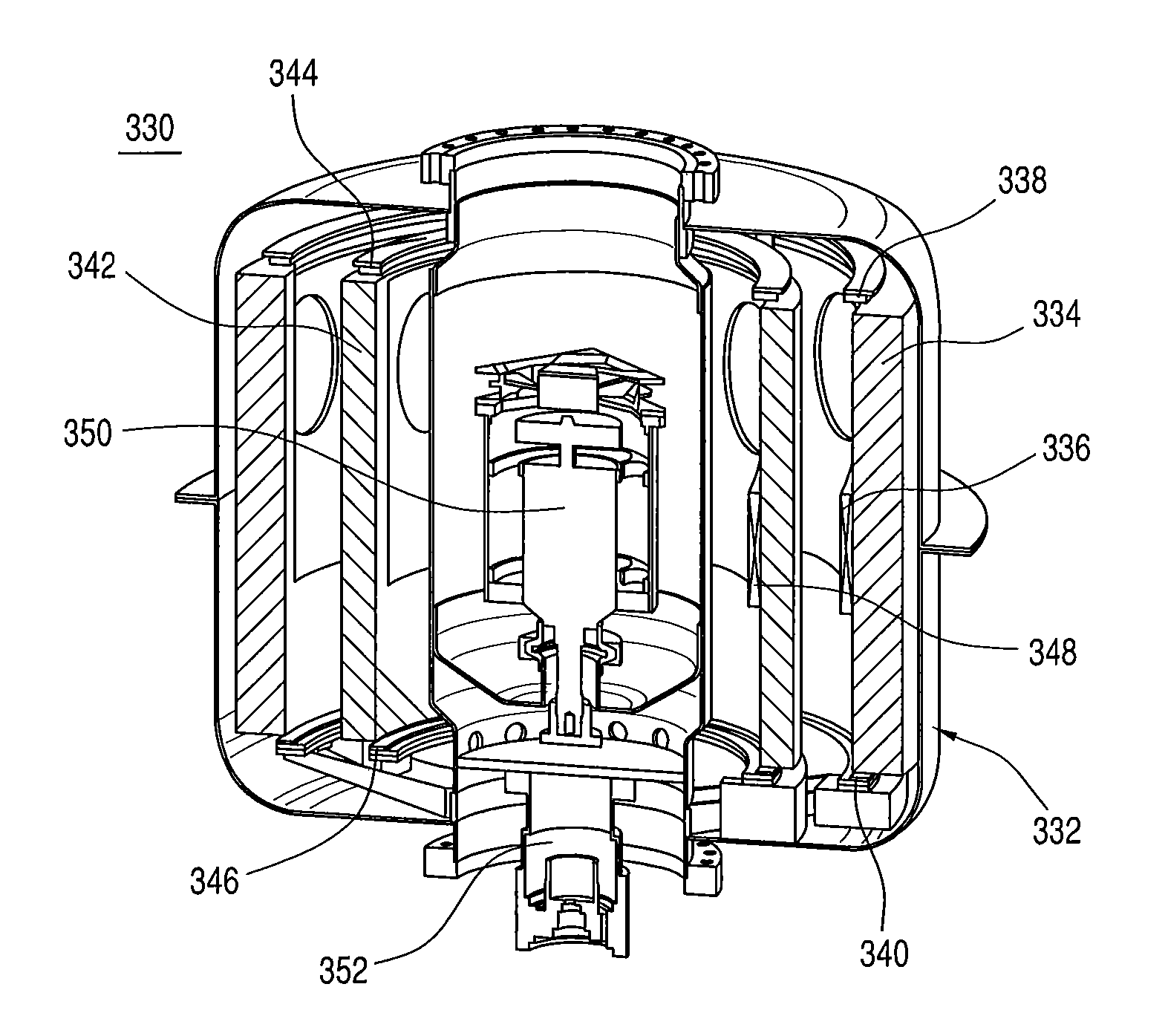
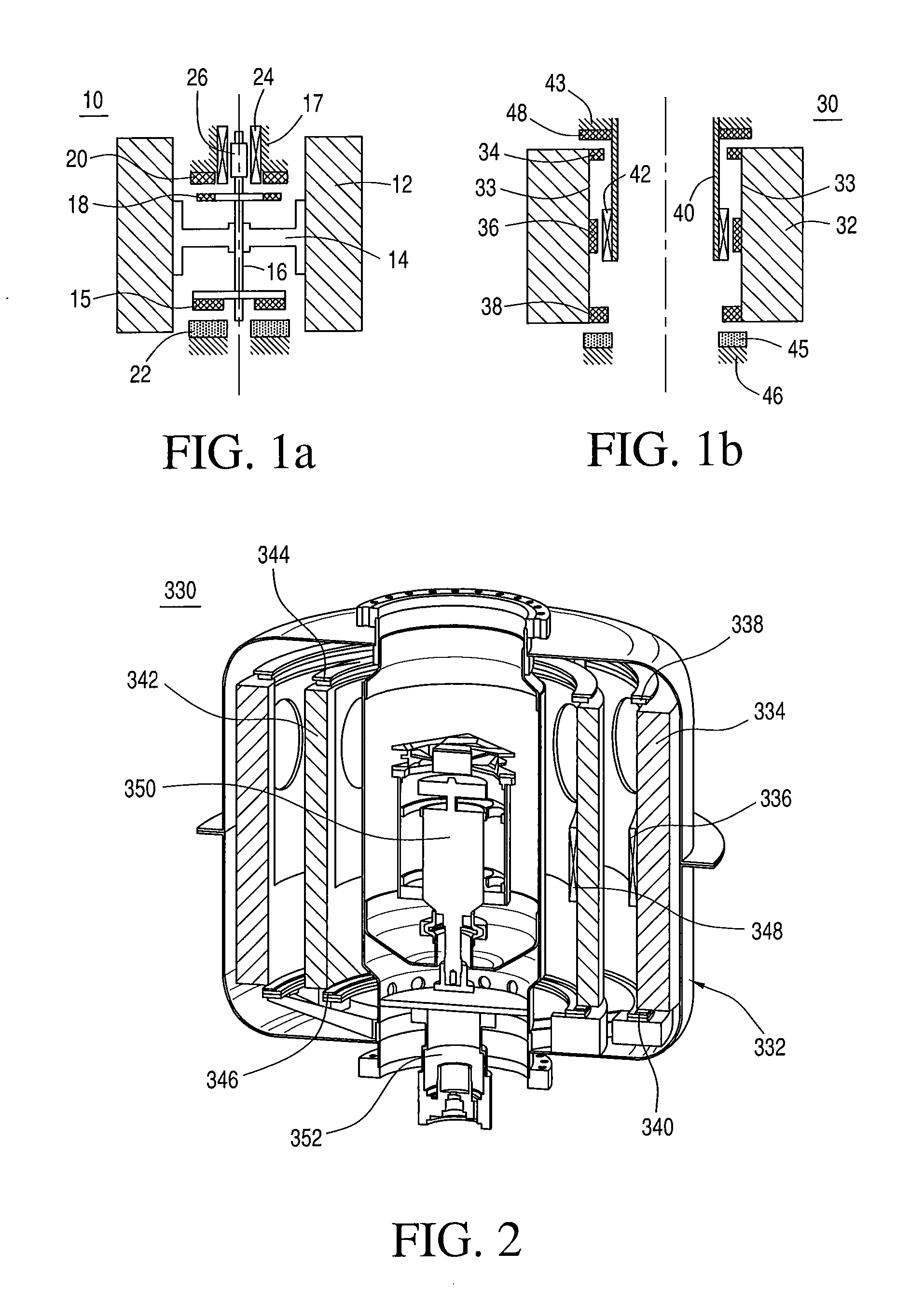
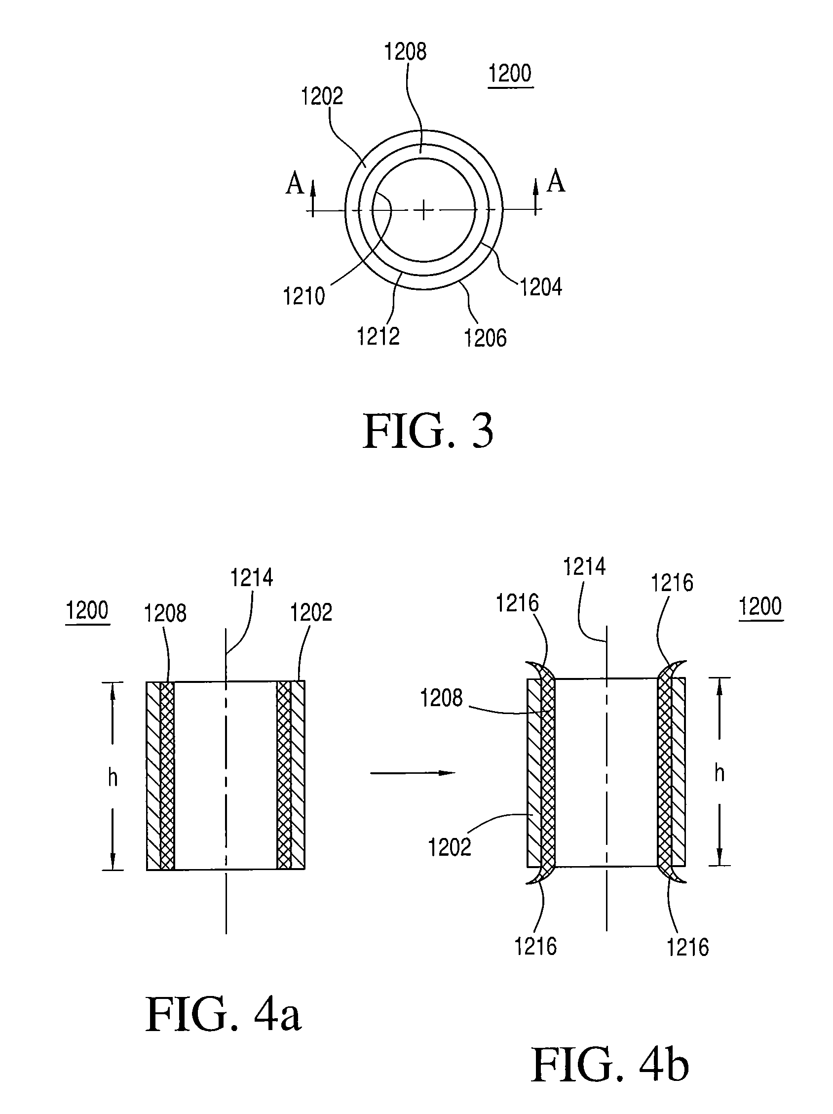
[0018]Some additional variations of the present disclosure will now be described more fully hereinafter with reference to the accompanying drawings, in which some, but not all variations of the disclosure are shown. Indeed, the present disclosure may be embodied in many different forms and should not be construed as limited to the variations and alternatives set forth herein. Instead, these illustrative variations are provided so that this disclosure will be thorough and complete, and will fully convey the scope of the disclosure to those skilled in the art. For example, unless otherwise indicated, referencing something as being a first, second or the like should not be construed to imply a particular order. Also, something may be described as being “above” something else and, unless otherwise indicated, may instead be “below”, and vice versa. Similarly, something described as being to the left of something else may instead be to the right, and vice versa. Like reference numerals re...


PUM

PropertyMeasurementUnit
circumferential velocitiesaaaaaaaaaa
thicknessaaaaaaaaaa

Abstract

Magnets and methods of their manufacture are disclosed for use in flywheel assemblies, such that the magnets comprise oriented fibers, such as, for example, axially-oriented fibers in a flexible rotor magnet composition to predictably allow the magnet to expand dimensionally upon rotation only in a predetermined and predictable fashion while maintaining critical contact with a rotor surface.

Description

TECHNOLOGICAL FIELD[0001]The present disclosure relates to flywheel energy storage devices and, more particularly, to hubless, or open-core flywheel storage devices having improved stability and performance.BACKGROUND[0002]Flywheel energy storage devices and systems are known for storing energy and releasing stored energy on demand. Known flywheel assemblies have a traditional rotor design sometimes made with carbon fiber composites. Such rotors have a shaft on which the motor / generator (M / G) and bearing permanent magnets (PMs) are mounted. The shaft is conventionally connected to the rim via a hub. The shaft-and-hub flywheel design is limited in terms of its achievable upper-end velocity. Matching useable materials for components in the flywheel assembly has been problematic since the radial growth and dimension of the components varies as the rotor velocity increases. The hub must mechanically couple the shaft to the rim without introducing bending modes into the rotor structure t...

Claims


Application Information

Patent Timeline
Patent Type & Authority Applications(United States)
IPC IPC(8): H02K1/27
CPCY10T29/49009F16F15/3156H02K1/02H02K1/27H02K7/025H02K2213/03F16C32/0438F16C2361/55F16C2360/45Y02E60/16
Inventor KOZAR, MICHAEL P.HULL, JOHN R.MITTLEIDER, JOHN A.WILENSKI, MARK S.
Owner THE BOEING CO
Why Eureka
Try Eureka