Demagnetization system and method

a technology of demagnetization system and electrode, applied in the direction of relays, electric heating, electric/magnetic/electromagnetic heating, etc., can solve the problems of arc blowing during welding, induction of residual magnetism within the pipes, defects in welds, etc., to reduce the likelihood of damage to the pipe, improve production efficiency, and reduce the effect of manpower and time was

Inactive Publication Date: 2011-05-05
SHAWCOR LTD
View PDF19 Cites 9 Cited by
  • Summary
  • Abstract
  • Description
  • Claims
  • Application Information

AI Technical Summary

Benefits of technology

[0012]In another embodiment the coil pair are arranged in a Helmholtz configuration. Advantageously, this results in the production of a substantially uniform field between the coils.
[0035]In one embodiment, the coil pair is substantially circular. In another embodiment, each of the coils in the coil pair is of substantially the same radius, “R”. The coil pair may have a diameter that is larger than the longest straight-line distance between any two points on the object, such that the object is able to pass through the area enclosed within each of the coil pair without obstruction.

Problems solved by technology

This results in the induction of residual magnetism within the pipes.
One major drawback associated with residual magnetism within the pipes is the problem of arc blowing during welding.
This may lead to the introduction of defects in the weld, which in turn compromises the mechanical properties of the weld.
Moreover, production efficiency is significantly reduced, as a large amount of time and resources must be employed to rectify the problems associated with defective welding.
A disadvantage of this method is that the demagnetization procedure is greatly influenced by surrounding conditions and may not be precisely reproduced.
Another disadvantage of this method lies in the fact that a lot of time is required for the approach to the resonance frequency.
The time required is so large that an efficient demagnetization of objects is not possible with a single pass-through method.
Besides also having a variety of parameters to manipulate, another drawback related to this method is that a complex control system may be required to control, synchronize and vary the pulse frequency, alternating polarity and repetition rate.
Moreover, most of the known methods and systems for demagnetization are limited for use in isolated objects and are not suitable for demagnetizing objects in an in-line production process, such as line-pipes.
The objects have to be manually removed from the process line and demagnetized in a separate step, which can be onerous and can increase the likelihood of the object being damaged due to the excessive amount of handling required.
It has also been shown that several of the known demagnetizing methods do not yield consistent results.
Moreover, known methods are particularly limited to the treatment of the ends of the pipes which does not necessarily solve the problem of residual magnetism completely.

Method used


Image

  • Demagnetization system and method
  • Demagnetization system and method
  • Demagnetization system and method

Examples


Embodiment Construction

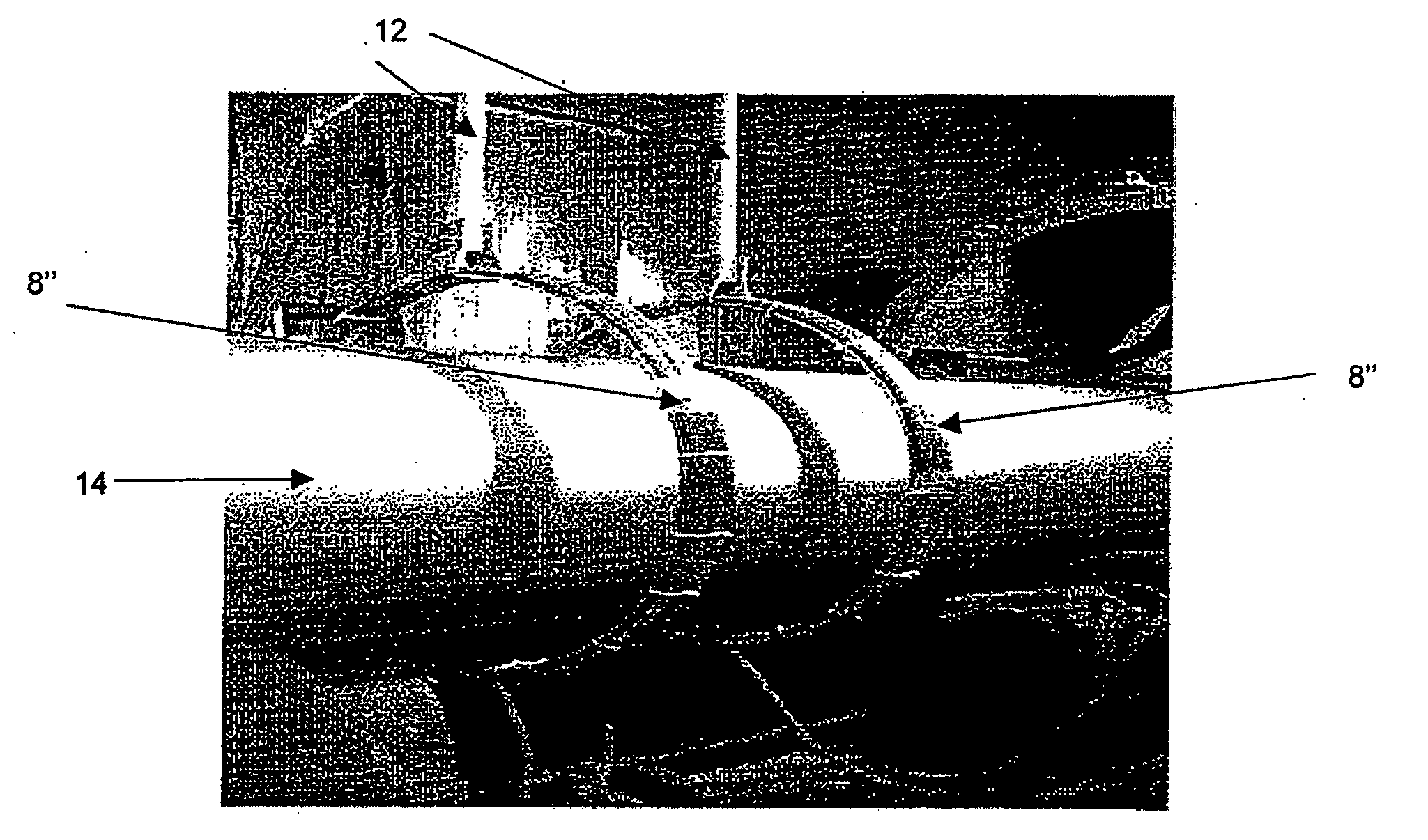
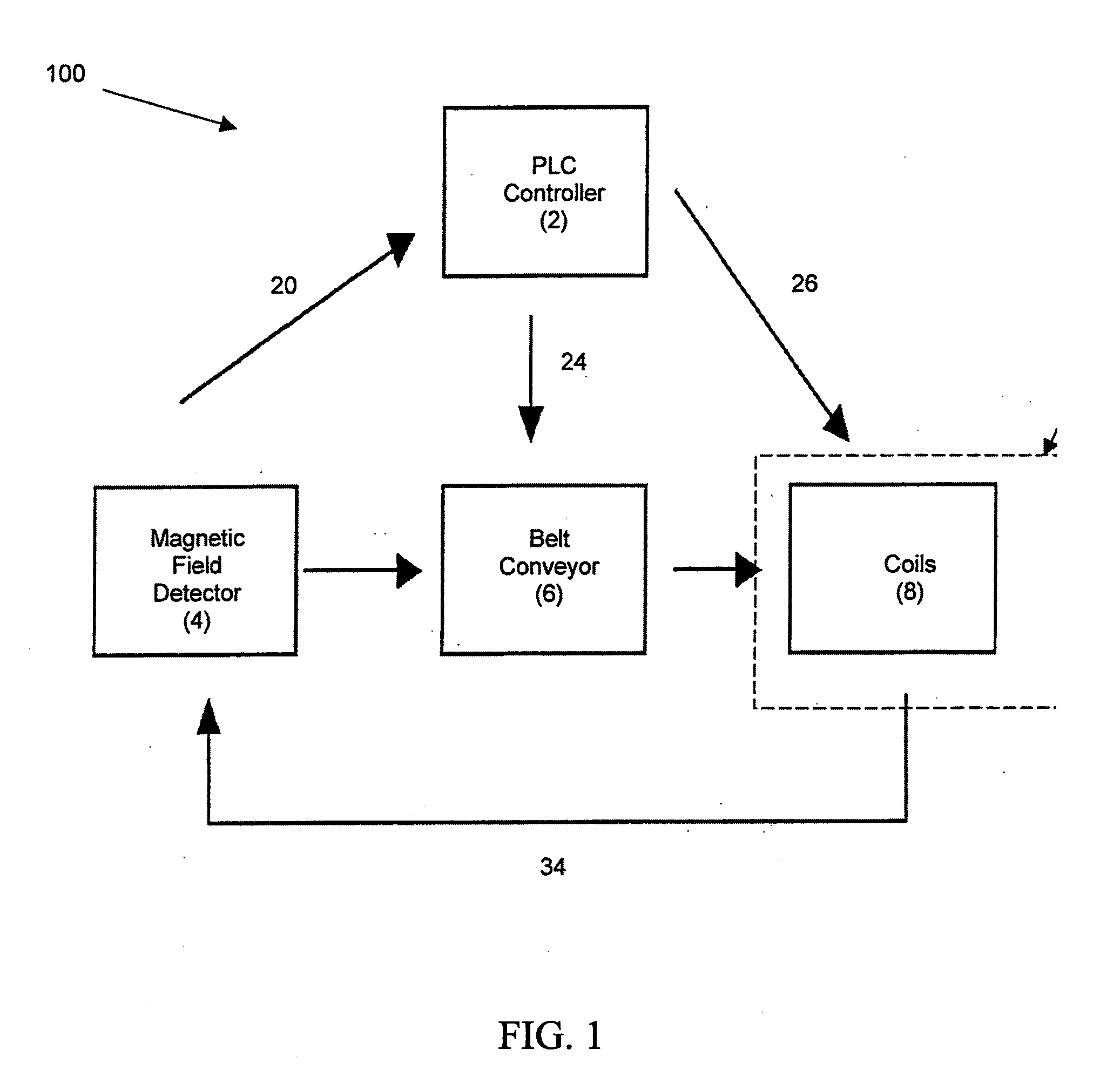
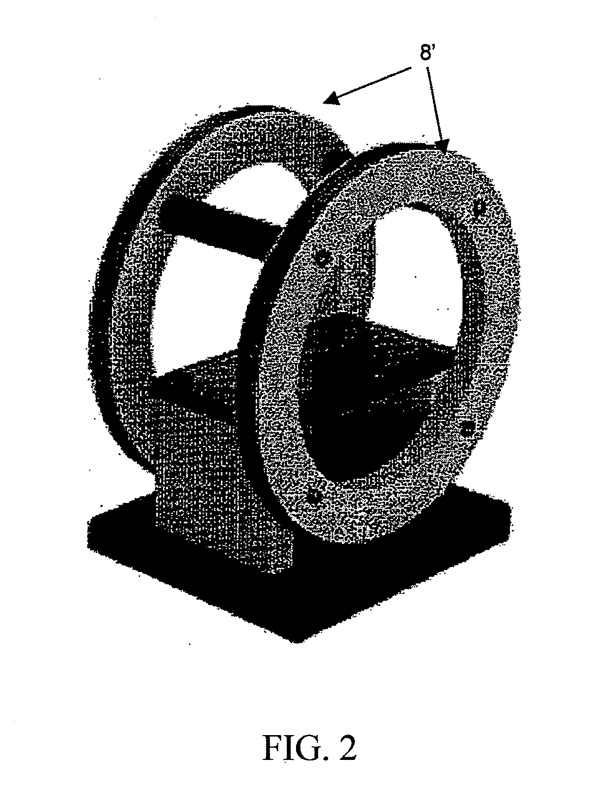
[0026]Exemplary, non-limiting embodiments of a demagnetization method, pipe production process and a demagnetization system will now be disclosed. The method comprising the step of applying a substantially uniform electromagnetic field to a magnetized object under conditions to substantially demagnetize said object.

[0027]In one embodiment, before the step of passing, said object is subjected to a heating step which causes said object to be magnetized. The heating step may be induction heating.

[0028]In one embodiment, the step of applying is carried out when said object is still on the production line of said object. The step of applying may be carried out at the start of the production line, at the end of the production line, in between the start and finish of the production line or all of the aforementioned. In another embodiment, the step of applying is carried out anywhere in the production line.

[0029]In one embodiment, the demagnetization method comprises the step of passing sai...


PUM

PropertyMeasurementUnit
electromagnetic fieldaaaaaaaaaa
degree of magnetizationaaaaaaaaaa
shapeaaaaaaaaaa

Abstract

There is disclosed a method and system for demagnetizing an object. The method includes the step of applying a substantially uniform electromagnetic field to a magnetized object under condition to substantially demagnetize said object.

Description

TECHNICAL FIELD[0001]The present invention generally relates to a method for demagnetizing an object such as a pipe. The present invention also relates to a system for performing the same.BACKGROUND[0002]Residual magnetism may be induced in conductive materials such as metal objects during its fabrication or manipulation where induction heating or electricity is applied. Residual magnetism is a major cause of concern for the pipe manufacturing and fabrication industries in which the fabrication of pipes occurs on an industrial scale. For example during the process of coating pipes, metal pipes are usually pre-heated using induction coils. This results in the induction of residual magnetism within the pipes. One major drawback associated with residual magnetism within the pipes is the problem of arc blowing during welding.[0003]Arc blowing is the phenomenon that occurs in direct current (DC) welding when the interaction between the magnetic field present in the pipes and welding arc ...

Claims


Application Information

Patent Timeline
Patent Type & Authority Applications(United States)
IPC IPC(8): H05B6/10H01F13/00
CPCH01F13/006
Inventor LIM, TEE YEN
Owner SHAWCOR LTD
Why Eureka
Try Eureka