

In-Vehicle Motor and Electric Power Steering Device Including the Same
a technology of electric power steering and in-vehicle motor, which is applied in the direction of electrical equipment, dynamo-electric machines, supports/enclosements/casings, etc., can solve the problems of difficult to ensure sufficient reliability against vibration, the connection structure is difficult to cope with the increasing number of coils,
- Summary
- Abstract
- Description
- Claims
- Application Information
AI Technical Summary
Benefits of technology
Problems solved by technology
Method used
Image

Examples
Embodiment Construction
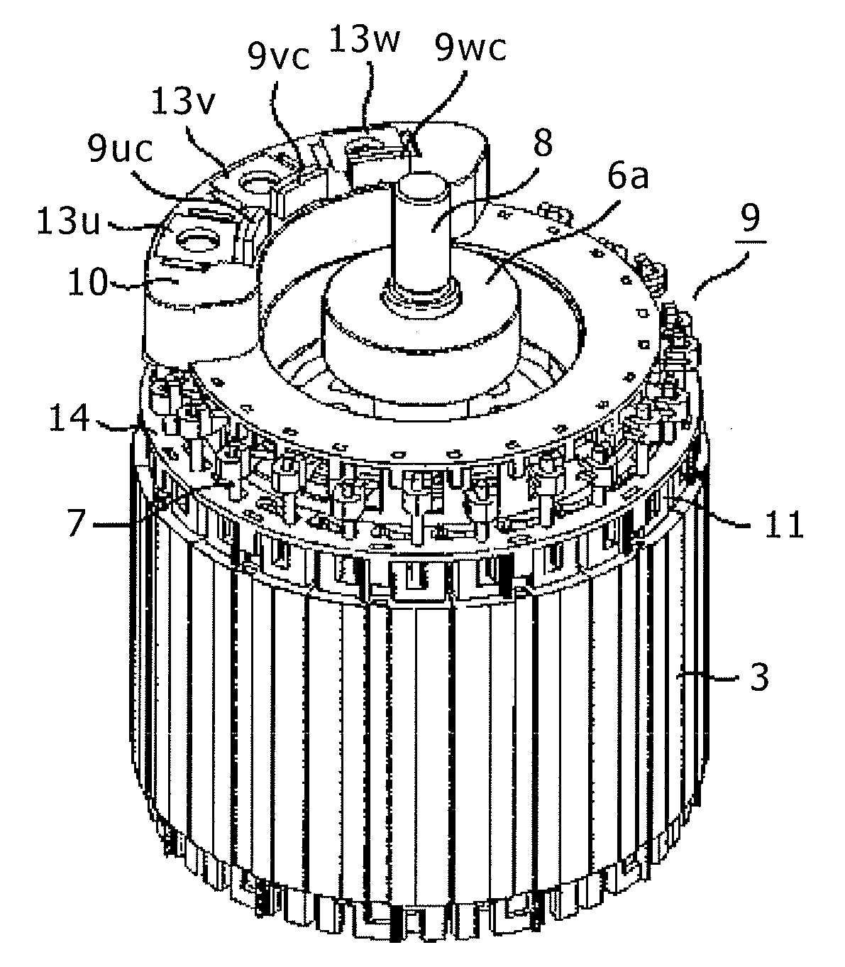
[0020]Hereinafter, an embodiment of the present invention will be described with reference to the accompanying drawings.
[0021]In in-vehicle motors, reductions in size and weight are desired, and therefore the number of poles tends to be increased for downsizing. Also, as for coils, rather than conventional distributed winding coils, concentrated winding coils capable of making a coil end smaller tend to be employed.
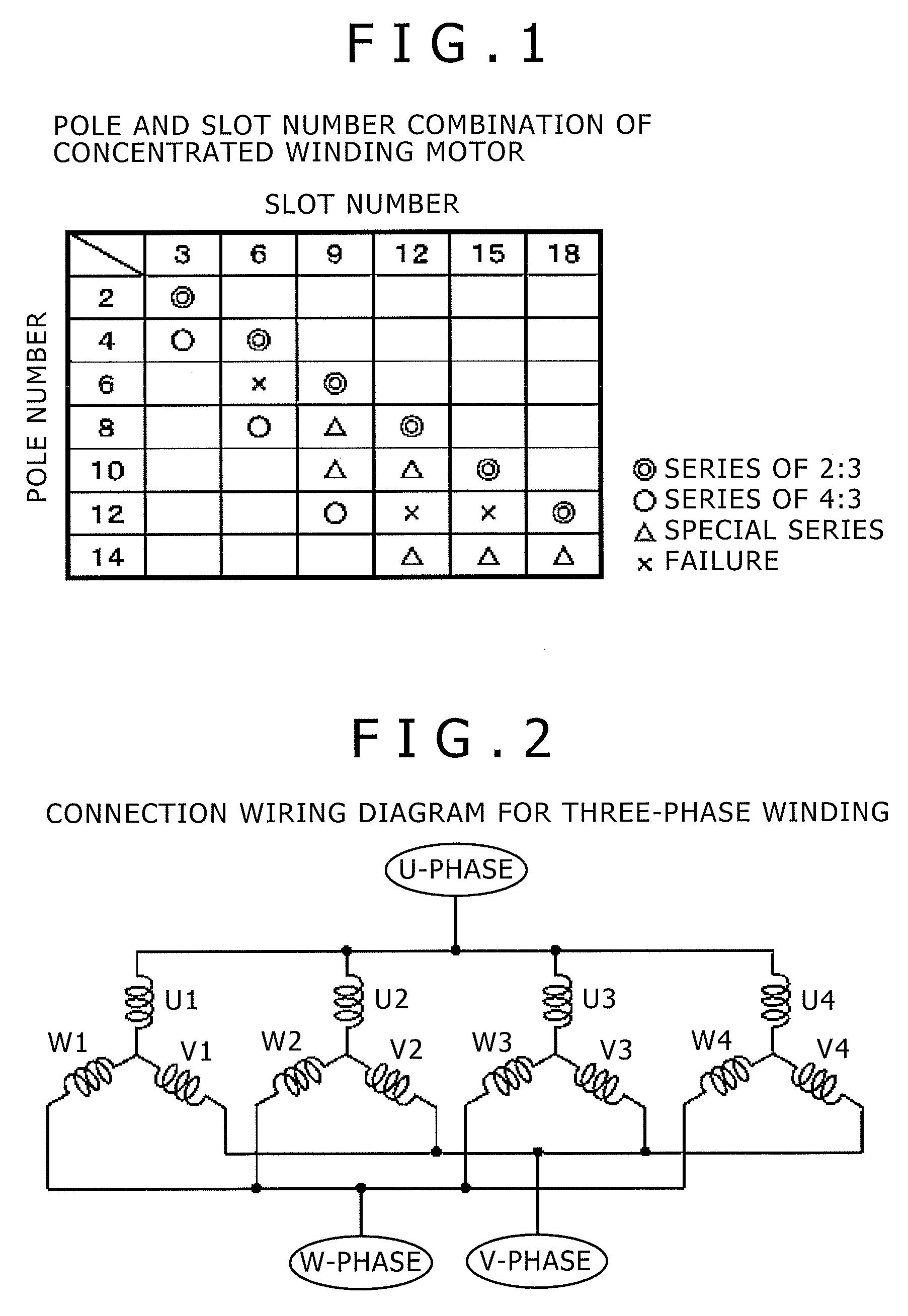
[0022]FIG. 1 shows the relationship between pole number and slot number of a concentrated winding motor. It is to be noted that, in the drawing, a double-circle denotes a combination for a series of 2:3; a circle, a series of 4:3; a triangle, a special series; and an x-mark, an exemplary combination in which the motor malfunctions.
[0023]As can be seen from FIG. 1, a series of 2:3 allowing selection of two poles each has a high degree of flexibility in design and widely used. For example, in electric power steering motors for automobile use, 8 poles and 12 slots are used. ...
PUM
 Abstract
Description
Claims
Application Information