Computer system, controller, controller manager and communication route analysis method

a communication route and controller technology, applied in the field of computer system, controller, controller manager, communication route analysis method, can solve problems such as rip and ospf, system cannot be said to be a system based on open flow protocol, and control function is not implemented, so as to avoid a large delay in communication route and measure a delay tim

Inactive Publication Date: 2013-10-03
NEC CORP
View PDF4 Cites 13 Cited by
  • Summary
  • Abstract
  • Description
  • Claims
  • Application Information

AI Technical Summary

Benefits of technology

[0020]According to the present invention, it is possible to measure a delay time in a communication route in a computer system using the ...

Problems solved by technology

However, such the route controlling function is not implemented in the above-mentioned system using the open flow protocol (hereafter, referred to as an OpenFlow system).
In this case, however, the communication route is set by the switch, and such the system cannot be said to be a system based on the open flow protocol.
Moreover, there are problems in t...

Method used


Image

  • Computer system, controller, controller manager and communication route analysis method
  • Computer system, controller, controller manager and communication route analysis method
  • Computer system, controller, controller manager and communication route analysis method

Examples


first exemplary embodiment

1. First Exemplary Embodiment

[0038](Configuration of Computer System)

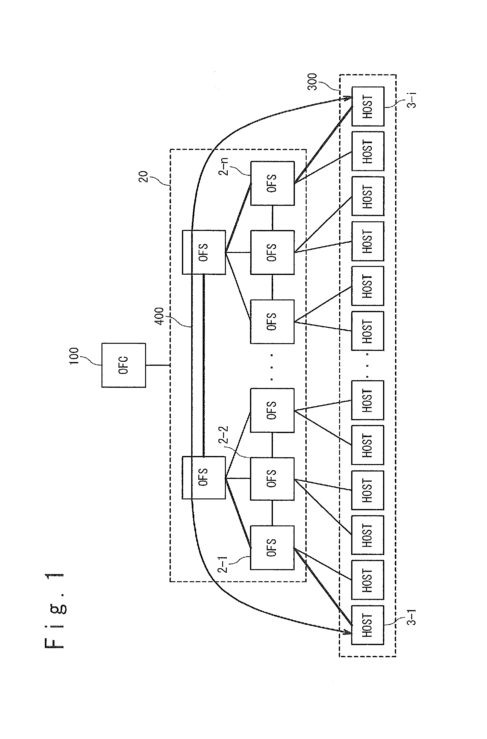
[0039]The computer system according to the present invention controls packet data forwarding by using the open flow technique, as in the case of the system shown in FIG. 1. In the computer system according to the first exemplary embodiment, a packet for delay measurement is forwarded through a master switch to a slave switch. A propagation time (delay time) between the switches is measured by using a reception time of the delay measurement packet that is notified as the first packet from the slave switch and a transmission time when the open flow controller transmits the packet.

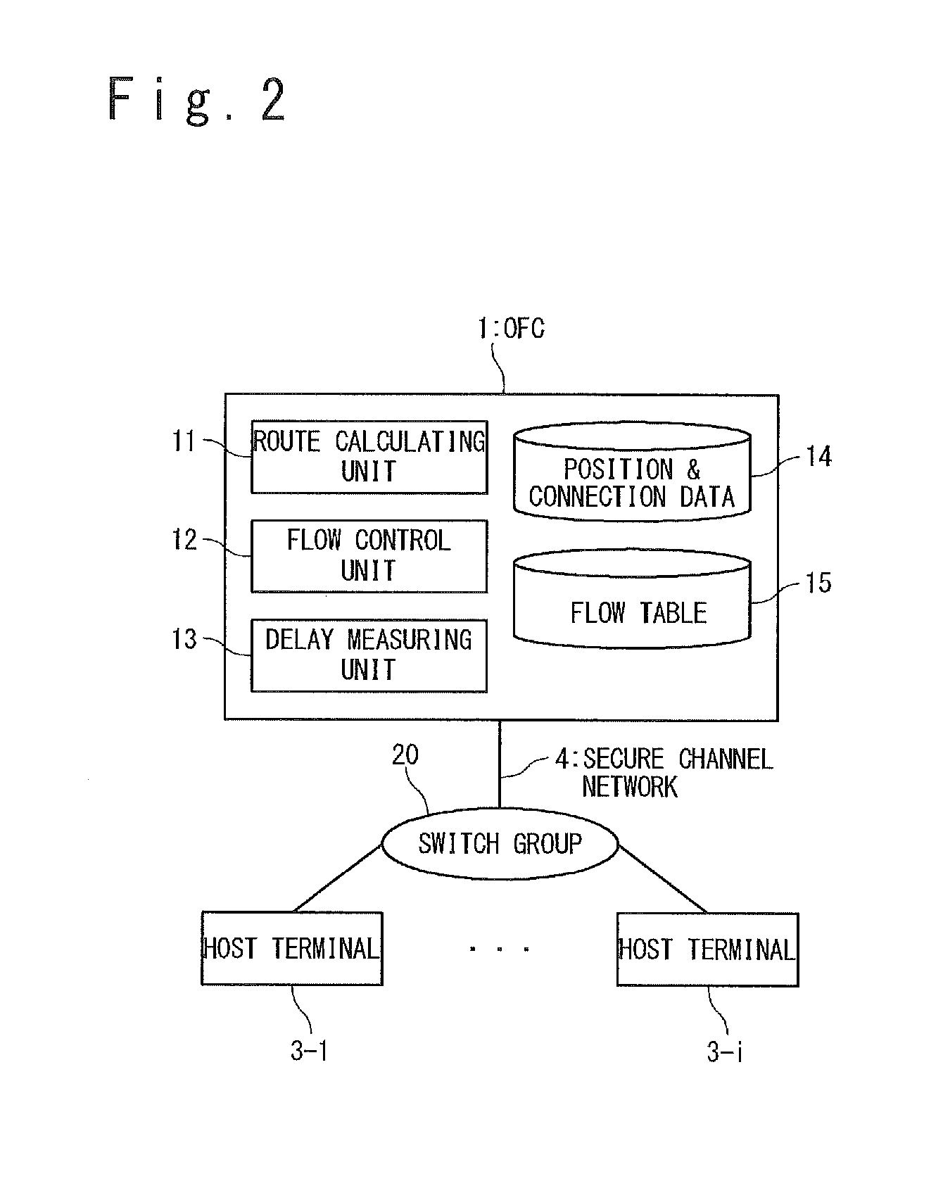
[0040]A configuration of the computer system in the first exemplary embodiment according to the present invention will be described with reference to FIGS. 2 to 9. As shown in FIG. 2, the computer system according to the present invention has: an open flow controller 1 (hereafter, referred to as an OFC 1), a switch group 20 that has a plural...

second exemplary embodiment

2. Second Exemplary Embodiment

[0102]The first exemplary embodiment is described with respect to the operation when the minimum delay route is retrieved and calculated between any two OFSs 2 in the network managed by one OFC 1. The second exemplary embodiment is described with respect to the computer system for retrieving the minimum delay route between any two OFSs 2 in networks managed by a plurality of OFCs, respectively.

[0103]FIG. 14 is a view showing a configuration of the computer system according to the second exemplary embodiment of the present invention. As shown in FIG. 14, the computer system in the second exemplary embodiment has an open flow controller manager 10 (OFC manager 10) and a plurality of OFCs 1′ (here, two OFCs 1′-1 and 1′-2 are shown as an example). Hereafter, when the OFC 1′-1 and 1′-1 are described without any discrimination, they are referred to as OFC 1′. The configuration of each of the networks managed the OFC 1′-1 and 1′-2 are similar to that in the fi...


PUM


Abstract

A controller sets, for a first switch, a flow entry whose rule is header information of a delay measurement packet and whose action is forwarding to a second switch, and transmits the delay measurement packet to the first switch. The first switch forwards the delay measurement packet received from the controller to the second switch, in accordance with the flow entry set in the first switch. An analyzing module obtains the delay measurement packet from the second switch and calculates a delay time in a communication section between the first switch and the second switch by using a time stamped on the delay measurement packet.

Description

TECHNICAL FIELD[0001]The present invention relates to a computer system, a controller, a controller manager, and a communication route analysis method. In particular, the present invention relates to a communication route analysis method in a computer system that uses an open flow protocol.BACKGROUND ART[0002]A technique (Open Flow) that controls a forwarding operation of each switch by an external computer in an integrated manner in a computer network is proposed by OpenFlow Consortium (refer to a Non-Patent Literature 1). A network switch (hereafter, referred to as an open flow switch (OFS)) supporting this technique retains detailed information such as a protocol type, a port number and the like in a flow table and thereby enables flow control and acquisition of statistic information. The flow table of the OFS in the network is set and managed by an open flow controller (OFC) in an integrated manner.[0003]A configuration and operation of a computer system that uses the open flow ...

Claims


Application Information

Patent Timeline
IPC IPC(8): H04L12/26H04L45/42
CPCH04L45/70H04L49/555H04L43/106H04L45/64H04L43/0852H04L43/20
Inventor GAO, FEIKAWAMOTO, MASAYA
Owner NEC CORP
Why Eureka
Try Eureka