
Method for wireless service handover and base station and relay station using the same

a wireless service and relay station technology, applied in the field of wireless service handover, can solve the problem of little time for handover decisions

Active Publication Date: 2013-10-03
IND TECH RES INST
View PDF8 Cites 21 Cited by
  • Summary
  • Abstract
  • Description
  • Claims
  • Application Information

AI Technical Summary

Benefits of technology

The present disclosure is about a wireless service handover scheme and a relay device and donor eNodeB using the same. The method involves detecting a handover target, measuring the received signal from the handover target, and determining if the moving device is approaching or leaving the target. The relay device, donor eNodeB, and a handover target have a processing circuit that performs these steps. The technical effects are improved wireless service handovers and better communication between the moving device and the handover target.

Problems solved by technology

However, for a typical high speed rail system, a mobile relay situated on a fast moving train would speed through an area of coverage provided by a DeNB in a very short period of time.
This means that as the train traverses along the train route, it would suffer from frequent handovers between DeNBs, and also a DeNB would have very little time to make handover decisions.

Method used


Image

  • Method for wireless service handover and base station and relay station using the same
  • Method for wireless service handover and base station and relay station using the same
  • Method for wireless service handover and base station and relay station using the same

Examples


Embodiment Construction

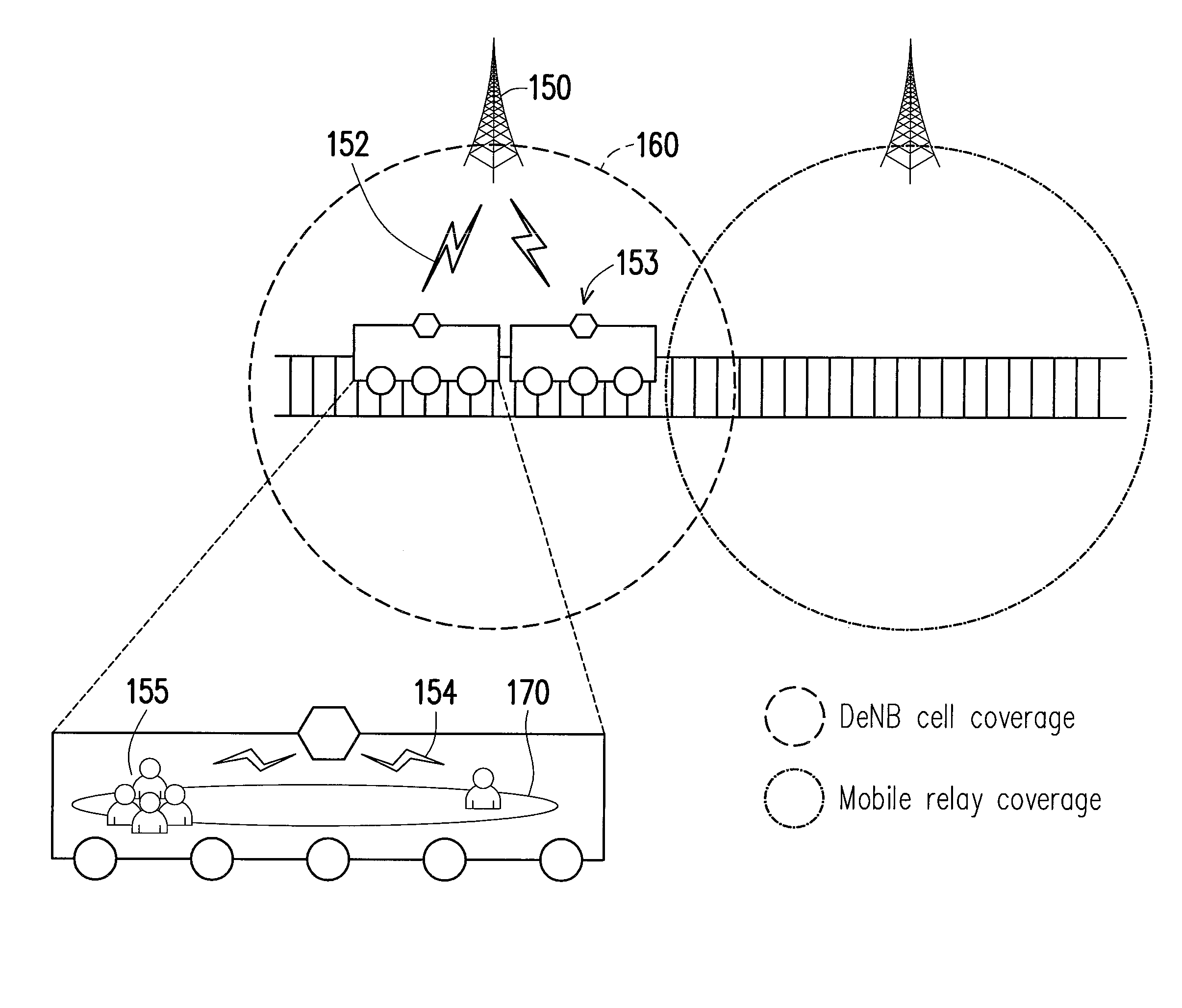
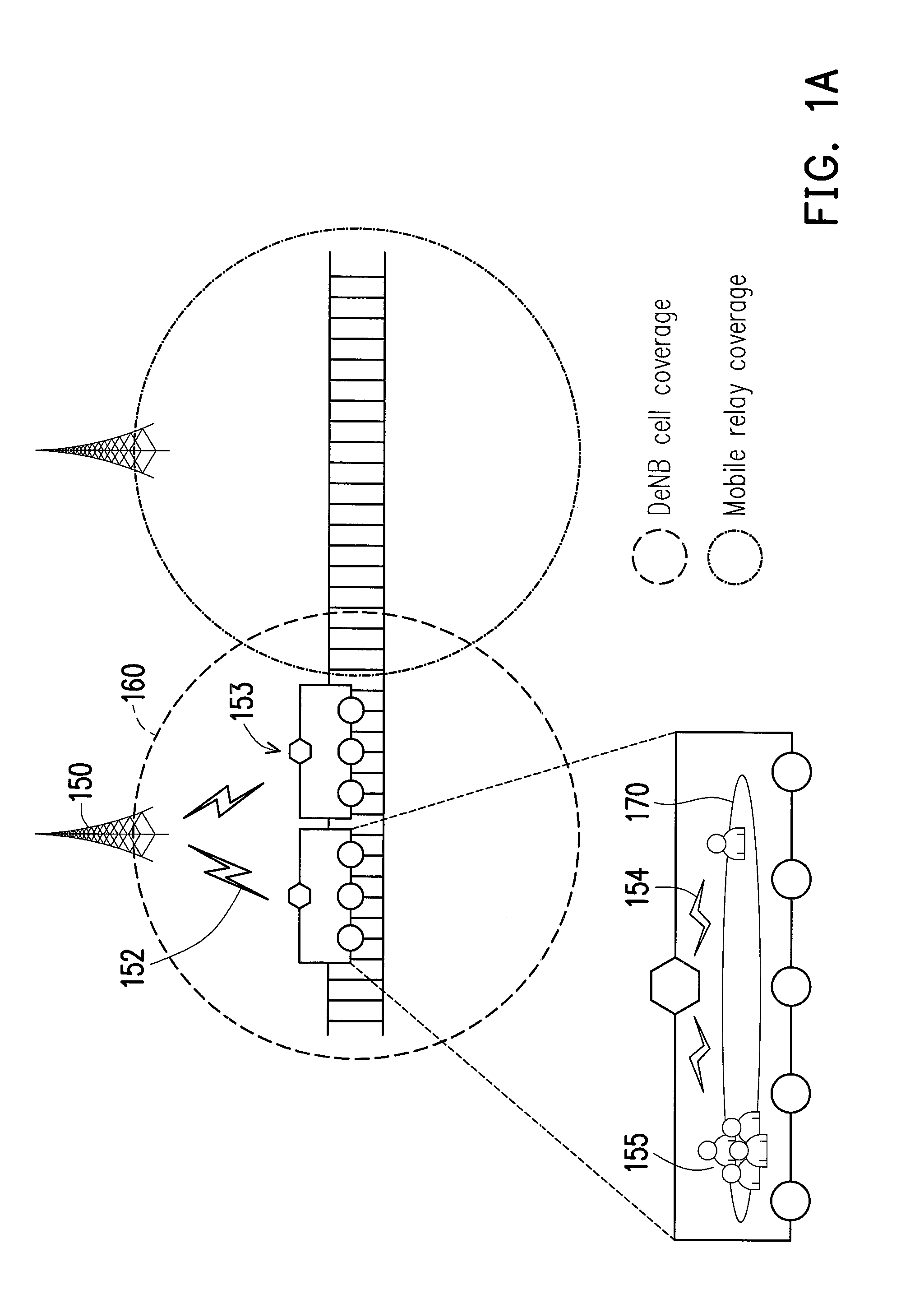
[0031]First, FIGS. 1A-1E provides an explanation for the concept upon which the present disclosure is premised upon. FIG. 1A serves as an example to illustrate the concept of providing the network coverage through a mobile delay. FIG. 1A shows a donor eNodeB (DeNB) 150 providing the network coverage within its coverage area 160 to at least one mobile relays 153 located in a train carriage. After a backhaul link 152 is established between the DeNB 150 and the mobile relay 153, the mobile relay may be able to provide the network coverage to at least one user equipments (UEs) 155 through an access link 154 between each UE and the mobile relay 153. The mobile relay 153 then serves as a base station to at least one UEs under its coverage 170.

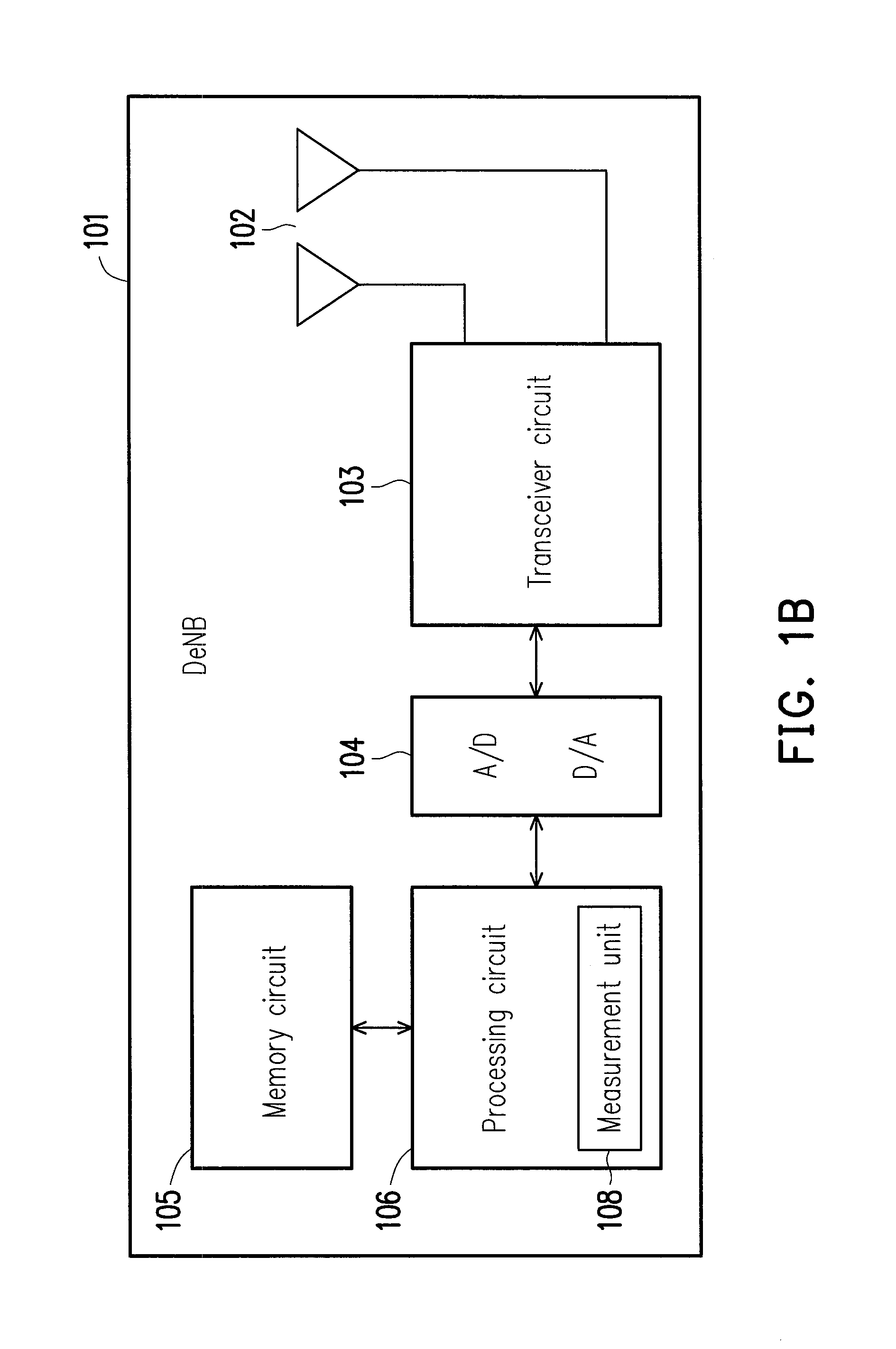
[0032]FIG. 1B shows an example of a functional block diagram of an DeNB used in the relay system of the present disclosure. Each DeNB 101 of the relay system may contain at least but not limited to a transceiver circuit 103, an analog-to-digital (A / D...


PUM


Abstract

A method, a mobile relay using the same and a DeNB using the same are proposed. The present disclosure reduces the time required to perform wireless service handover by detecting the movement status of the mobile relay relative to a candidate DeNB as to determine whether a mobile relay is approaching or leaving a candidate handover DeNB. By incorporating the movement status into a report sent to the serving DeNB, the serving DeNB would require less time to make handover decisions since the reporting interval could be reduced to one interval, and the time to trigger would not be required. The movement status could be determined based on the propagation time of signals, a list of neighbor cell information, or the Doppler effect.

Description

CROSS REFERENCE TO RELATED APPLICATION[0001]This application claims the priority benefit of U.S.A. provisional application Ser. No. 61 / 618,853 filed on Apr. 2, 2012. The entirety of the above-mentioned patent application is hereby incorporated by reference herein and made a part of specification.BACKGROUND[0002]1. Technical Field[0003]The present disclosure generally relates to a wireless service handover scheme, a relay station using the same and a donor eNodeB using the same.[0004]2. Related Art[0005]Recently, as many countries continue to build their high speed rail systems, mobile relay techniques have been considered for the IMT-advanced system in order to support wireless communication services within a high speed rail system in which mobile relays situated on a train carriage could relay network services from nearby base stations to users. The mobile relay which functions as a hub or a repeater may then provide the network coverage of a base station to users in a train throug...

Claims


Application Information

Patent Timeline
Patent Type & Authority Applications(United States)
IPC IPC(8): H04W36/32
CPCH04B7/2606H04W84/047H04W36/32H04W36/0009H04W36/326
Inventor PAN, MENG-SHIUANLIN, TZU-MING
Owner IND TECH RES INST
Learn More