
Relative ordering circuit synthesis

a technology of relative ordering and circuits, applied in the field of circuit synthesis, can solve the problems of large amount of resources and time, laborious, and faster automated synthesis methods, and achieve the effect of reducing labor intensity and time, and reducing labor intensity

Inactive Publication Date: 2013-10-03
GLOBALFOUNDRIES US INC
View PDF2 Cites 82 Cited by
  • Summary
  • Abstract
  • Description
  • Claims
  • Application Information

AI Technical Summary

Benefits of technology

This patent describes a system that can automatically create a circuit design using a processor and memory device. The system can generate a structure that tells where different parts of the circuit should go based on the layout of the circuit. It can then place those specific parts of the circuit in the correct position and decide what other parts of the circuit should be placed. This system can make it easier to design complex circuits and improve their overall efficiency.

Problems solved by technology

Custom development methods may provide the best results, but are labor intensive and require a large amount of resources and time.
Alternatively, automated synthesis methods may be faster; however, they may not produce the most efficient circuits.
For example, automated design processes may not achieve the same component density as a custom design process.

Method used


Image

  • Relative ordering circuit synthesis
  • Relative ordering circuit synthesis
  • Relative ordering circuit synthesis

Examples


Embodiment Construction

[0022]It will be readily understood that the components of the embodiments, as generally described and illustrated in the figures herein, may be arranged and designed in a wide variety of different configurations in addition to the described example embodiments. Thus, the following more detailed description of the example embodiments, as represented in the figures, is not intended to limit the scope of the claims, but is merely representative of those embodiments.

[0023]Reference throughout this specification to “embodiment(s)” (or the like) means that a particular feature, structure, or characteristic described in connection with the embodiment is included in at least one embodiment. Thus, appearances of the phrases “according to embodiments” or “an embodiment” (or the like) in various places throughout this specification are not necessarily all referring to the same embodiment.

[0024]Furthermore, the described features, structures, or characteristics may be combined in any suitable ...


PUM


Abstract

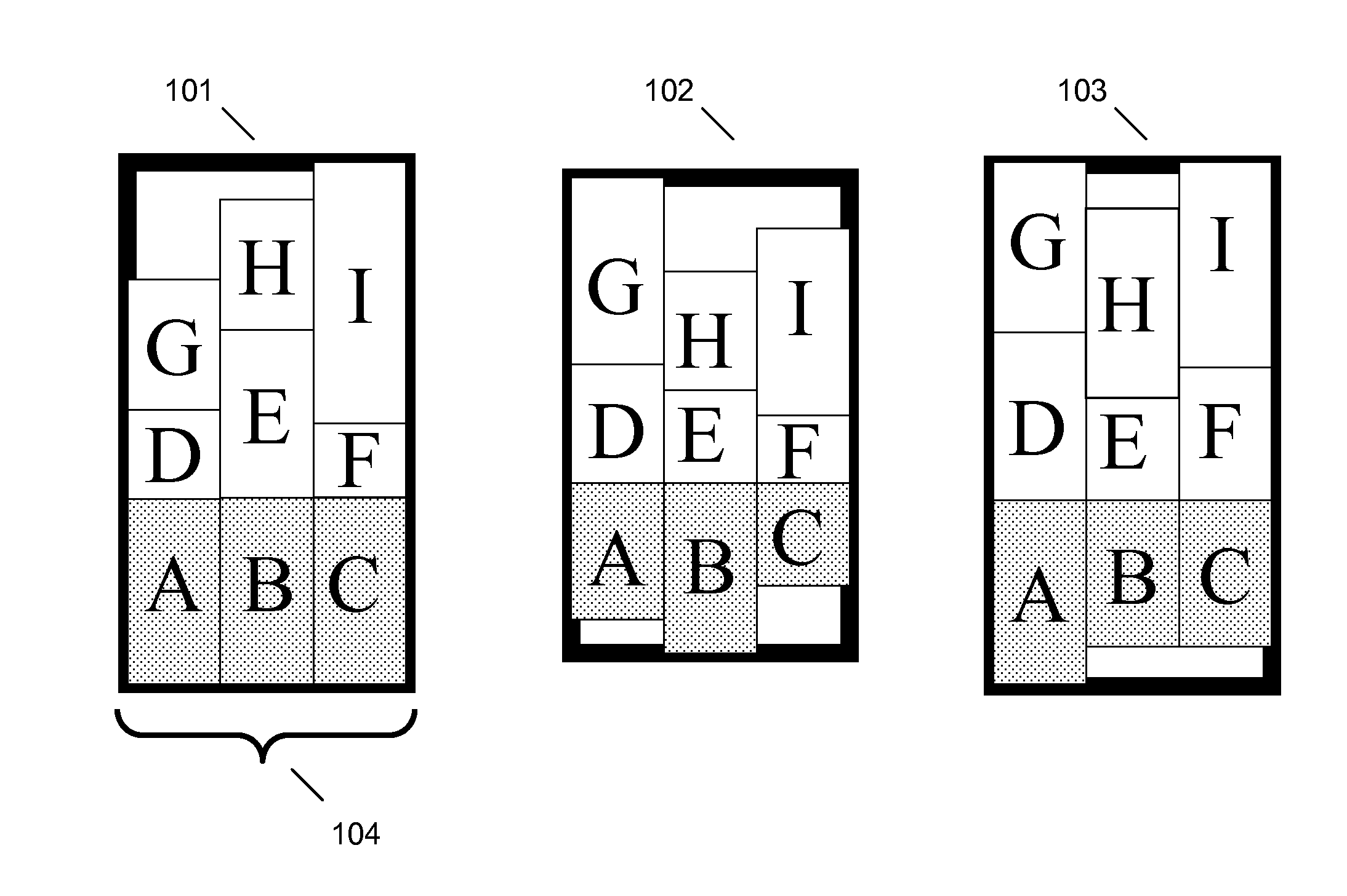
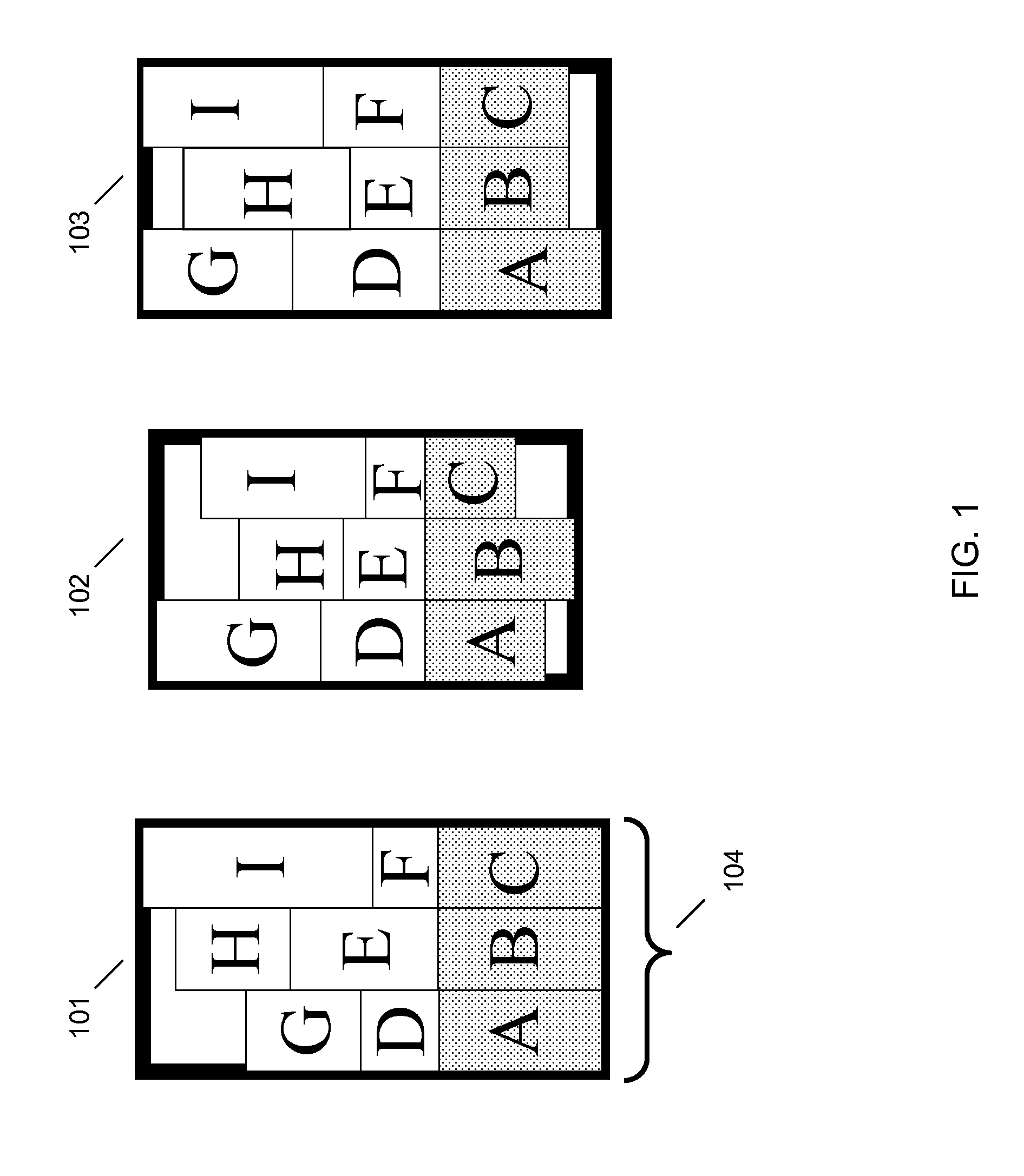
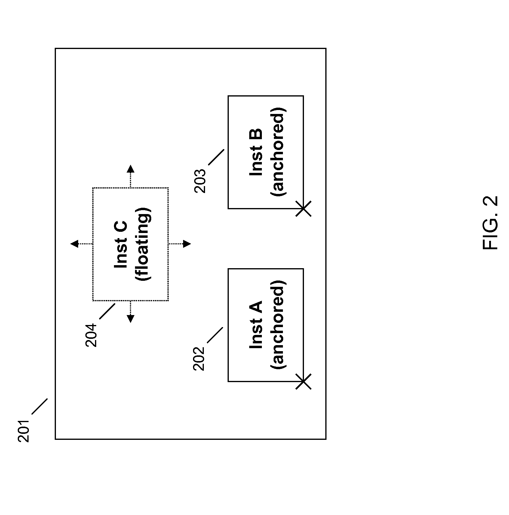
Systems and methods for relative ordering circuit synthesis are provided herein. One aspect provides for generating at least one circuit design via at least one processor accessible by a computing device; wherein generating at least one circuit design comprises: generating at least one relative order structure based on at least one circuit design layout, the at least one relative order structure comprising at least one placement constraint associated with at least one circuit element; placing the at least one circuit element associated with the at least one placement constraint within a circuit design according to the at least one placement constraint; and placing circuit elements not associated with the at least one placement constraint within the circuit design. Other embodiments and aspects are also described herein.

Description

FIELD OF THE INVENTION[0001]The subject matter presented herein generally relates to circuit synthesis and processes for custom automated circuit synthesis in particular.BACKGROUND[0002]Circuit synthesis involves generating electronic circuits comprised of multiple components that implement a specific circuit behavior. In general, the circuit components consist of different sizes and types of logic gates arranged in a highly specified manner. Circuits may be designed according to custom development methods or automated synthesis processes, such as through computer aided design tools that determine circuit component placement. Custom development methods may provide the best results, but are labor intensive and require a large amount of resources and time. Alternatively, automated synthesis methods may be faster; however, they may not produce the most efficient circuits. For example, automated design processes may not achieve the same component density as a custom design process.BRIEF...

Claims


Application Information

Patent Timeline
Patent Type & Authority Applications(United States)
IPC IPC(8): G06F17/50
CPCG06F2217/06G06F17/5072G06F2111/04G06F30/392
Inventor CHO, MINSIKPURI, RUCHIRREN, HAOXINGTANG, XIAOPINGXIANG, HUAZIEGLER, MATTHEW MANTELL
Owner GLOBALFOUNDRIES US INC
Learn More