Adjustable damping valve device

Active Publication Date: 2013-10-10
ZF FRIEDRICHSHAFEN AG
View PDF7 Cites 12 Cited by
  • Summary
  • Abstract
  • Description
  • Claims
  • Application Information

AI Technical Summary

Benefits of technology

This patent describes a valve system that includes a pressure-relief valve and an emergency operation valve. These valves are connected to a common flow-off opening, which helps to guide the flow of the valve system. The arrangement of the pressure-relief valve in a receiving channel parallel to the movement direction of the valve body makes it easy to produce an axial channel. The inflow into the pressure-relief valve takes place via the pressure compensation channel of the valve body. This design prevents blockages and ensures proper functioning of the valve system. The technical effects of this patent are simplified installation and a more efficient and reliable valve system.

Problems solved by technology

This poses the problem that a malfunction of the emergency operation valve also affects the damping force setting of the auxiliary valve.
The construction principle in FIG. 2 and FIG. 6 presents the difficulty that the axially movable valve body of the auxiliary valve and the emergency operation valve body are in direct contact, and the emergency operation valve carries out a displacing movement on the valve body of the auxiliary valve starting from the emergency operation position into the normal operation position.
This results in small annular gaps which, on the one hand, bring about internal leakage which influences the damping force adjustment and, on the other hand, impair the guiding of the valve body relative to the magnetic coil.
These difficulties can be overcome, but the expenditure on fabrication required for this purpose adds to production costs.
However, this radial arrangement of the pressure-relief valve affects both the radial and axial installation space of the damping valve device.

Method used


Image

  • Adjustable damping valve device
  • Adjustable damping valve device
  • Adjustable damping valve device

Examples


Embodiment Construction

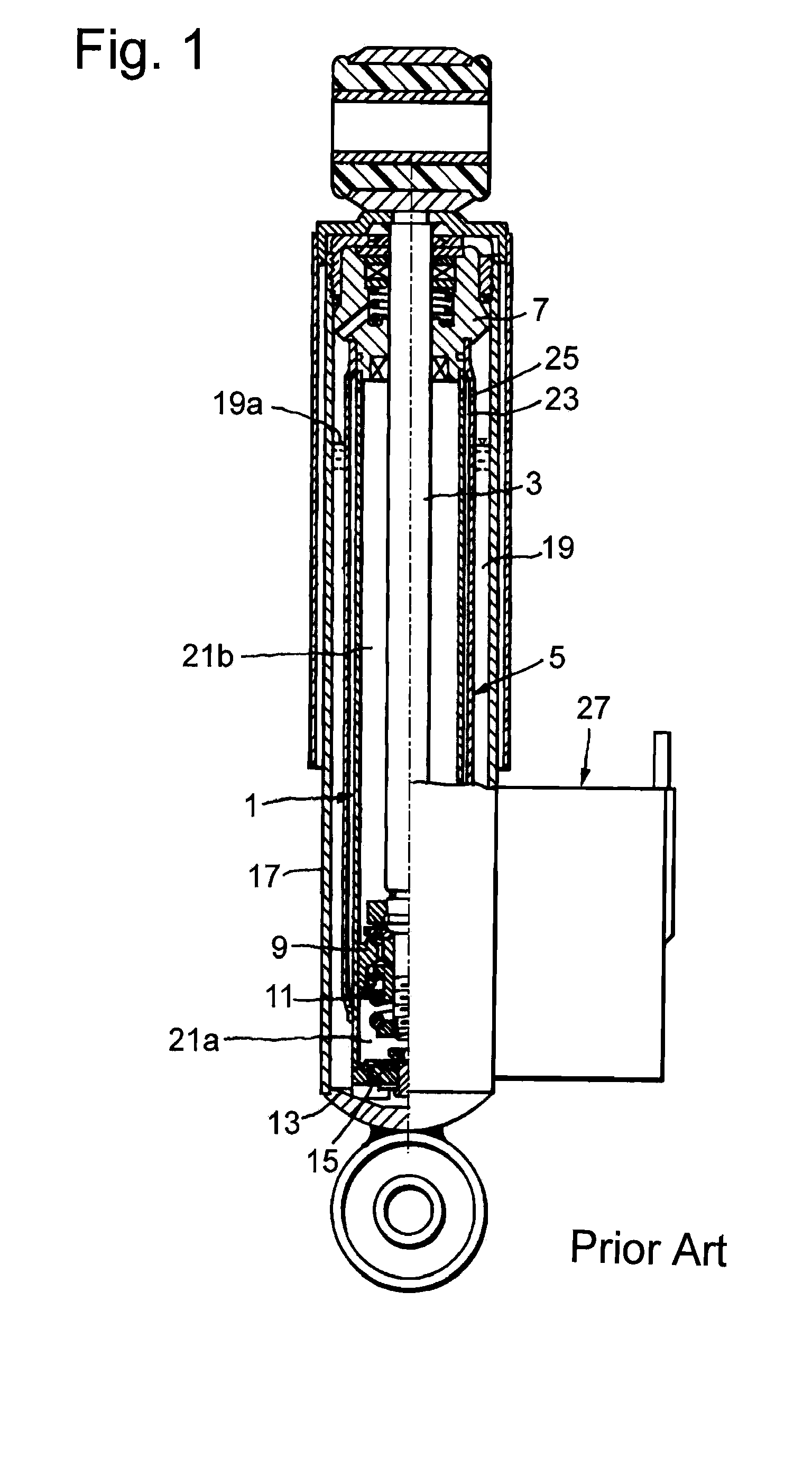
[0022]In FIG. 1, a vibration damper has a cylinder 1 in which a piston rod 3 is arranged so as to be axially movable. A guiding and sealing unit 7 guides the piston rod 3 out of the upper end of the cylinder. A piston unit 9 with a piston valve arrangement 11 is fastened to the piston rod 3 inside the cylinder 1. The bottom end of the cylinder 1 is closed by a base plate 13 with a bottom valve arrangement 15. The cylinder 1 is enclosed by a reservoir tube 17. The reservoir tube 17 and an intermediate tube 5 form an annular space 19 presenting a compensation chamber. The space within the cylinder 1 is divided by the piston unit 9 into a first working chamber 21a and a second working chamber 21b. The working chambers 21a and 21b are filled with damping fluid. The compensation chamber 19 is filled with liquid up to level 19a and, above that, with gas. A first line section, namely, a high-pressure section 23 which communicates with the second working chamber 21b via a bore 25 of cylinde...


PUM


Abstract

An adjustable damping valve device (27), in particular for a vibration damper, comprises a first valve (47) and an emergency operation valve (61), both of which are actuated by magnetic force. The emergency operation has a valve body (61) which is preloaded in a closed position by at least one valve spring. A pressure-relief valve (85) is connected hydraulically in parallel with the emergency operation valve (61) so that the damping force is determined by the pressure-relief valve (85) when the emergency operation valve (61) is closed. The pressure-relief valve (85) is arranged in the valve body (63) of the emergency operation valve.

Description

PRIORITY CLAIM[0001]This is a U.S. national stage of application No. PCT / EP2011 / 070437, filed on Nov. 18, 2011. Priority is claimed on the following applications: Country: Germany, Application No.: 10 2010 063 386.0, Filed: Dec. 17, 2010, the content of which is incorporated herein in its entirety by reference.FIELD OF THE INVENTION[0002]The invention is directed to an adjustable damping valve device particularly for a vibration damper.BACKGROUND OF THE INVENTION[0003]Depending upon the design principle, a damping valve which is adjustable by means of magnetic force adopts a particularly soft or a particularly hard damping force characteristic in deenergized state. This effect is produced at least by a spring force against which the magnetic force must act. In case of outage of the magnetic force, e.g., due to cable breakage, the spring force then displaces a valve body into an end position. Assuming that a high damping force also represents high safety reserves for the chassis of a...

Claims


Application Information

Patent Timeline
IPC IPC(8): G05D16/04
CPCF16F9/464G05D16/04F16F2230/24Y10T137/7793F16F9/14F16F9/34F16F15/023F16F15/03F16F2222/06F16F2222/12
Inventor FORSTER, ANDREAS
Owner ZF FRIEDRICHSHAFEN AG
Why Eureka
Try Eureka