Transverse flux machine utilized as part of a combined landing gear system

a transverse flux machine and landing gear technology, applied in the direction of dynamo-electric machines, energy-saving operation measures, electrical apparatus, etc., can solve the problems of raised reliability and operational concerns, mechanical complexity, and never been used in aircraft landing gear applications

Inactive Publication Date: 2013-10-10
HAMILTON SUNDSTRAND CORP
View PDF5 Cites 8 Cited by
  • Summary
  • Abstract
  • Description
  • Claims
  • Application Information

AI Technical Summary

Problems solved by technology

All of this has resulted in mechanical complexity, and has raised reliability and operational concerns.
However, transverse flux machines have never been utilized in aircraft landing gear applications.

Method used


Image

  • Transverse flux machine utilized as part of a combined landing gear system
  • Transverse flux machine utilized as part of a combined landing gear system
  • Transverse flux machine utilized as part of a combined landing gear system

Examples


Embodiment Construction

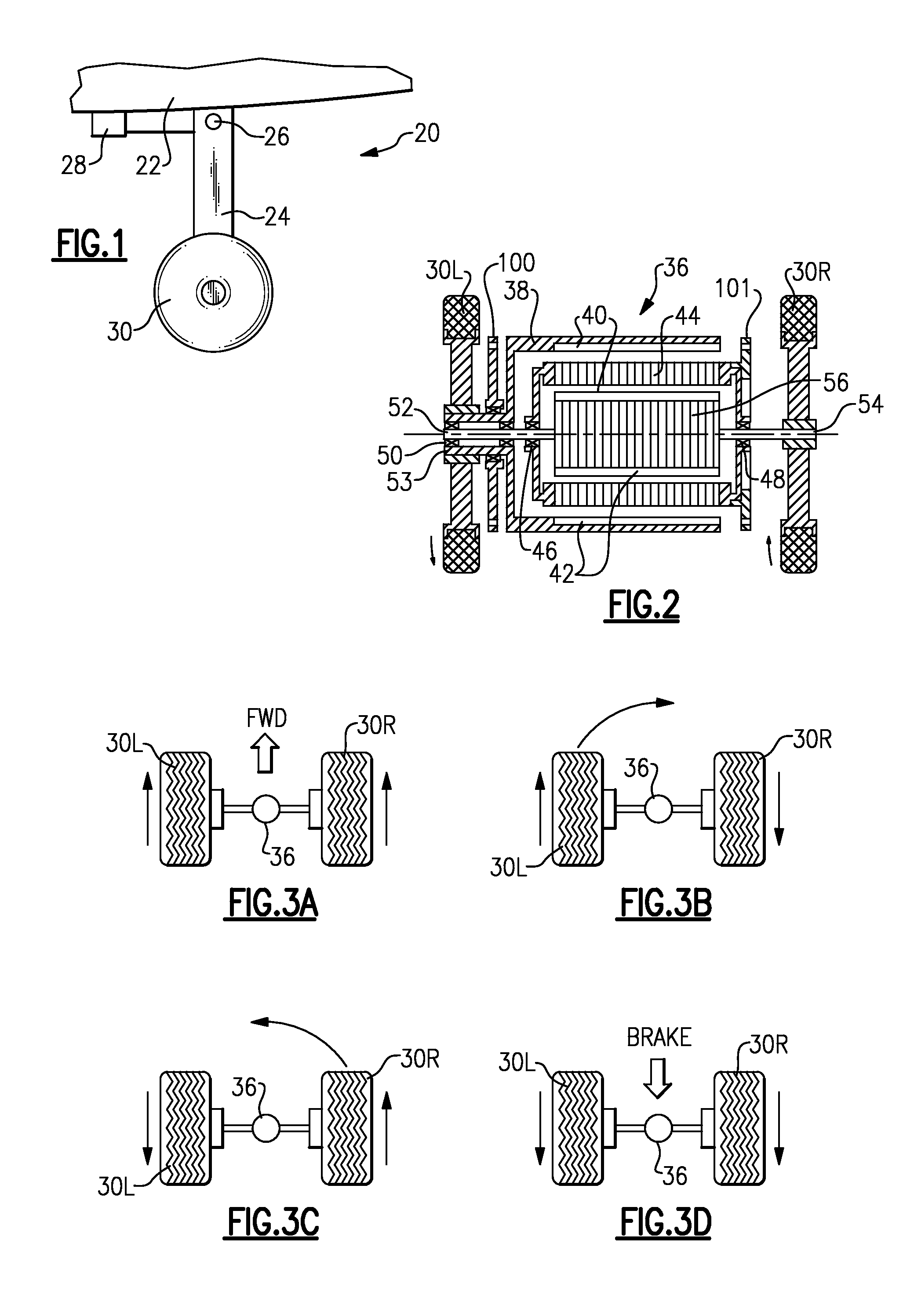
[0020]FIG. 1 shows an aircraft 20 including an aircraft body 22 having a deployable and retractable landing gear 24. A pivot point 26 is shown associated with an actuator 28, which schematically refers to the ability for the landing gear 24 to be pulled to a stowed position within the vehicle body 22, or extended to the illustrated landing position. A nose wheel 30 is shown.

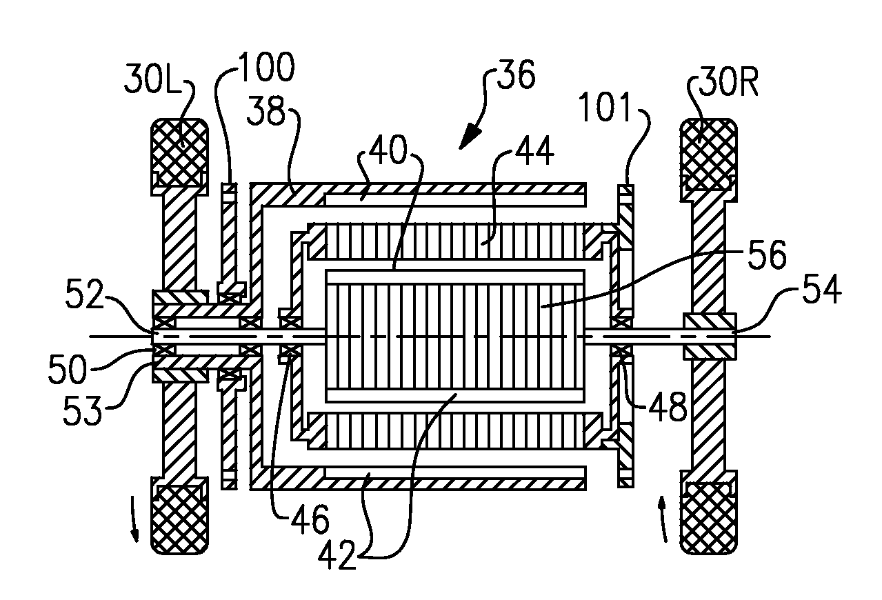
[0021]As shown in FIG. 2, there are actually two nose wheels, with a left nose wheel 30L and a right nose wheel 30R.

[0022]A permanent magnet motor, including a stator 44 is mounted on a shaft 52 / 54 rotating with a rotor 56. The stator 44 is mounted on bearings 46 and 48 on the shaft 52 / 54, respectively. The stator 44 is supported by a static support. The shaft 54 is attached to rotate with the wheel 30R.

[0023]A second rotor 38 is shown as part of the drive and steering arrangement 36. The rotor 38 includes a shaft 53. A pair of bearings 50 supports shaft 53 on shaft 52 in a cantilever manner. The rotor 38 is fixe...


PUM


Abstract

A landing gear for an aircraft has a set of axially spaced wheels rotatable about a common axis drive by a transverse flux drive. In another feature, a transverse flux drive includes a first rotor and a second rotor. One of the first and second rotors is positioned radially inwardly of the other. A single stator is positioned radially intermediate the first and second rotors. In another feature, a landing gear combination for use on an aircraft has a nose wheel assembly including at least one nose wheel to be associated with a nose cone on an aircraft. A main landing gear assembly is also associated with the aircraft. A transverse flux motor provides on-ground propulsion and / or braking to the aircraft.

Description

BACKGROUND OF THE INVENTION[0001]This application relates to a steering and drive arrangement which simplifies a landing gear assembly for an aircraft.[0002]Aircraft are typically provided with a pair of nose wheel tires which are deployable from the underside of the frame as part of the landing gear. The nose wheel tires must steer the aircraft, and must also be retractable and deployable.[0003]To provide steering the prior art has typically required some form of hydraulic steering mechanism, and associated valves, controls, etc. Further, a lubrication system has often been required for the steering system. A drive arrangement is also required.[0004]In addition, aircraft are typically provided with main landing wheels under the wings or under the fuselage of the aircraft that typically do not turn. The main landing wheels provide braking force, and also may sometimes provide on-ground propulsion of the aircraft. As such, they have large drive apparatus. These large drive apparatus ...

Claims


Application Information

Patent Timeline
Patent Type & Authority Applications(United States)
IPC IPC(8): B64C25/50H02K16/02
CPCB64C25/405Y02T50/823B64C25/50Y02T50/80
Inventor RIBAROV, LUBOMIR A.GIERAS, JACEK F.
Owner HAMILTON SUNDSTRAND CORP
Why Eureka
Try Eureka