Electric Induction Heat Treatment of Electrically Conductive Thin Strip Material

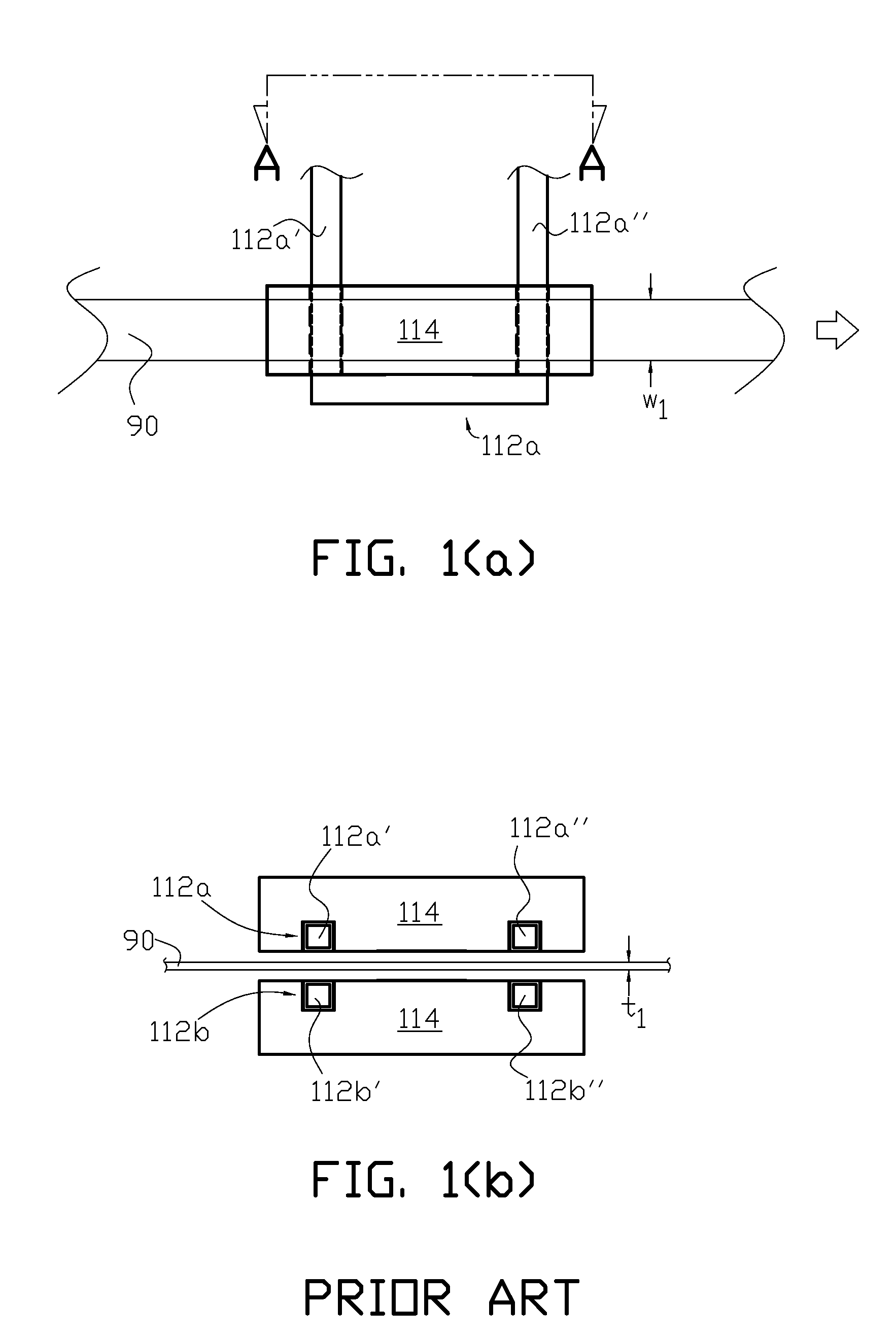
a technology of electrical induction heat treatment and thin strip material, which is applied in the direction of heat treatment apparatus, lighting and heating apparatus, furniture, etc., can solve the problems of poor efficiency of the arrangement shown in fig. 1(i>a/i>) and fig. 1(i>b/i>)

Inactive Publication Date: 2011-02-17
RADYNE CORP
View PDF11 Cites 21 Cited by
  • Summary
  • Abstract
  • Description
  • Claims
  • Application Information

AI Technical Summary

Problems solved by technology

When the thin strip comprises a material with low resistivity (high conductivity) such as a copper strip, the arrangement shown in FIG. 1(a) and FIG. 1(b) is not very efficient.

Method used


Image

  • Electric Induction Heat Treatment of Electrically Conductive Thin Strip Material
  • Electric Induction Heat Treatment of Electrically Conductive Thin Strip Material
  • Electric Induction Heat Treatment of Electrically Conductive Thin Strip Material

Examples


Embodiment Construction

[0017]While the present invention will be described in connection with a preferred embodiment, it will be understood that it is not intended to limit the invention to that embodiment. On the contrary, it is intended to cover all alternatives, modifications and equivalents as may be included within the scope of the invention.

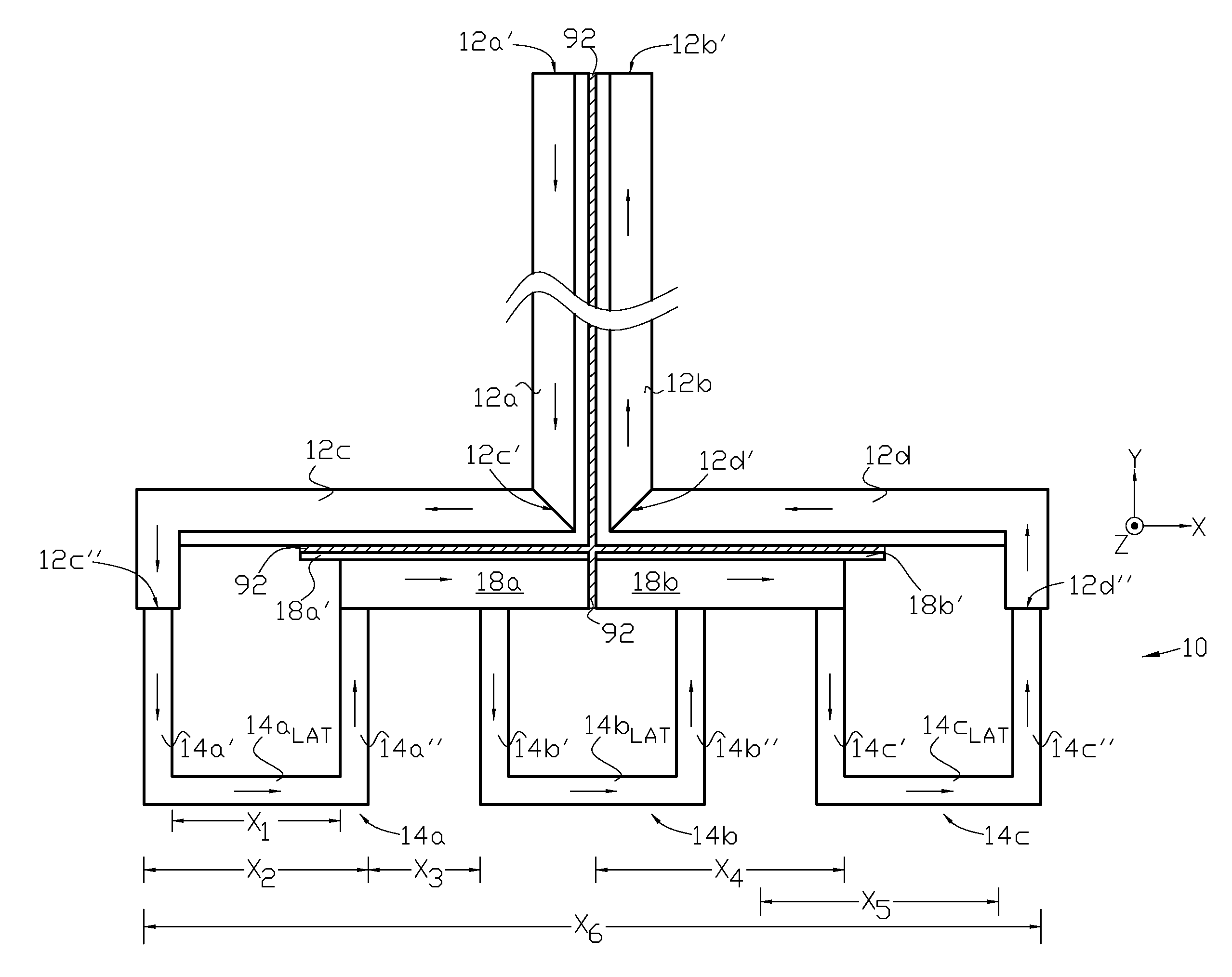
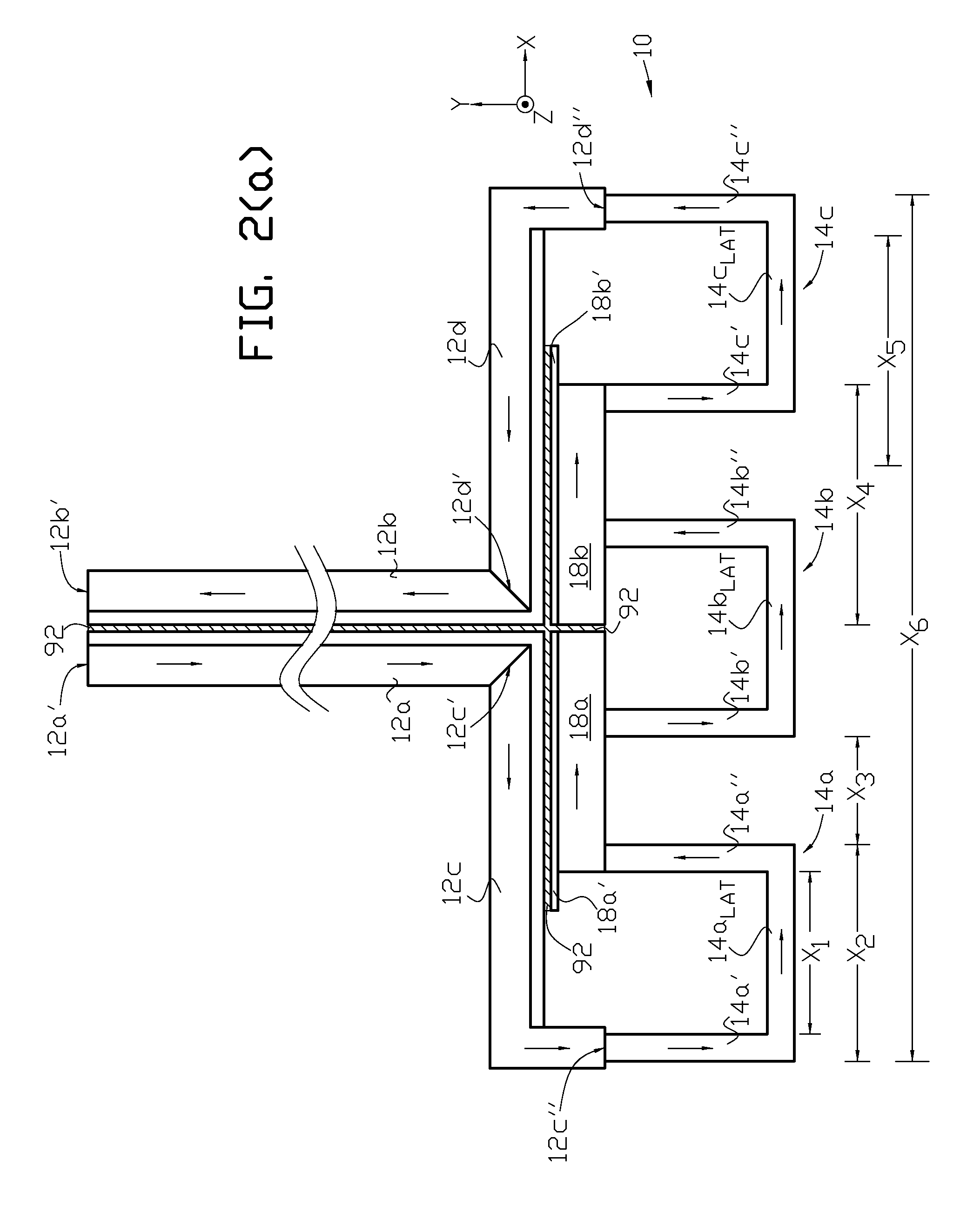
[0018]One example of the induction coils used in the transverse flux induction heating apparatus, or inductor assembly, of the present invention is illustrated in FIG. 2(a) and FIG. 2(b). Power supply feeder electrical conductors 12a and 12b (separated by dielectric 92 shown with crosshatching) are suitably connected either directly or indirectly to a single phase source of AC current at ends 12a′ and 12b′. The power supply feeder conductors spread apart in the indicated X-direction via branch electrical conductors 12c and 12d, which in this example of the invention are substantially perpendicular to the feeder electrical conductors, and have facing adjacent ends...


PUM

PropertyMeasurementUnit
thicknessaaaaaaaaaa
electrical resistivityaaaaaaaaaa
frequenciesaaaaaaaaaa

Abstract

Apparatus and method are provided for electric induction heat treatment of electrically conductive thin strip material. Multiple series-connected coil loops, each having a pole pair, are provided in each of a top and bottom induction coil, which are positioned mirror image to each other. The top and bottom induction coils form a transverse flux induction heat treatment apparatus. A separate flux concentrator is provided over and on the side of each pole. The thin strip material passes between the poles of the top and bottom induction coils and the flux concentrators associated with each of the poles.

Description

CROSS-REFERENCE TO RELATED APPLICATIONS[0001]This application claims the benefit of U.S. Provisional Application No. 61 / 232,976 filed Aug. 11, 2009, which is hereby incorporated by reference in its entirety.FIELD OF THE INVENTION[0002]The present invention relates to electric induction heat treatment of electrically conductive thin strip materials.BACKGROUND OF THE INVENTION[0003]A known apparatus for electric induction heat treatment of thin strip material is illustrated in FIG. 1(a) and FIG. 1(b). A pair of induction coils 112a and 112b form a transverse flux inductor. Each coil has two transverse poles; coil 112a has poles 112a′ and 112a″, and coil 112b has poles 112b′ and 112b″. Thin strip 90 is positioned between the pair of coils. The thin strip may have a width, w1, for example, of 7 / 16th of an inch and a thickness, t1, of 0.01-inch. A single flux concentrator 114 is typically positioned over and around the two poles of each coil as shown in the figures. When a suitable alter...

Claims


Application Information

Patent Timeline
Patent Type & Authority Applications(United States)
IPC IPC(8): H05B6/04H05B6/36
CPCC21D1/42C21D9/60F27D99/0006F27D11/06F27B9/067Y02P10/25
Inventor WARNER, GREGG G.PARKER, JAMES D.MORTIMER, JOHN JUSTIN
Owner RADYNE CORP
Why Eureka
Try Eureka