Electric machine with soft magnetic teeth

a technology of electric machines and magnetic teeth, applied in the direction of dynamo-electric machines, electrical apparatus, magnetic circuits, etc., can solve the problems of gap in the circumferential direction between, and achieve the effect of reducing winding losses

Inactive Publication Date: 2005-11-01
HILL WOLFGANG
View PDF11 Cites 25 Cited by
  • Summary
  • Abstract
  • Description
  • Claims
  • Application Information

AI Technical Summary

Benefits of technology

[0019]Example: Compared to a conventional machine where the pole core width equals the groove width in the middle of the groove area, the pole core width, at equal flux density in the air gap, can be increased by 15% by fabricating the pole segments from grain oriented electric sheet. Additionally, thanks to the more advantageous winding technique, the pole coil can be made with a 65% instead of a 50% space factor. In total, a 50% larger copper cross section surface per groove or, respectively, a decrease of winding losses of 33% is achieved.
[0020]Essential for this improvement is the segmentation of the wound soft magnetic body into spooled poles and non-spooled half-poles where the half-pole constitutes at least one tooth at the air gap surface. The spooled pole and the two half-poles connected to the same in the yoke area are a magnetic unit that is separated from adjacent identical magnetic units by non-magnetic holding elements. The teeth of the half-poles separated by the holding element are more distant from each other in direction of the movement than the teeth within the magnetic unit and thereby generate a phase offset between adjacent magnetic units.

Problems solved by technology

This results in gaps in circumferential direction between the radially inner ends of the cores which are wider than the width of the cores themselves.

Method used


Image

  • Electric machine with soft magnetic teeth
  • Electric machine with soft magnetic teeth

Examples


Embodiment Construction

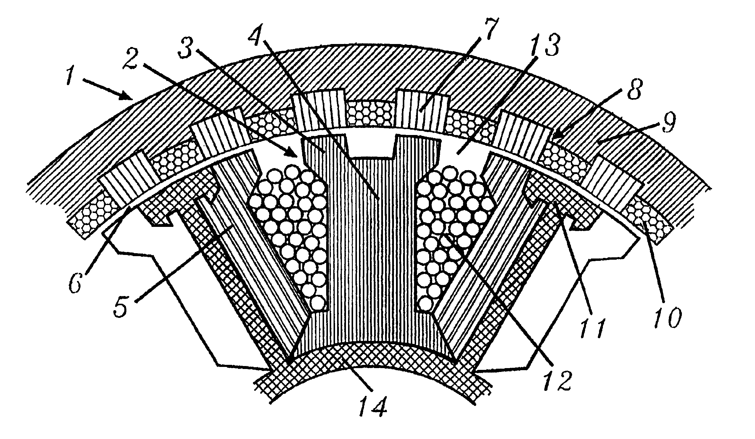
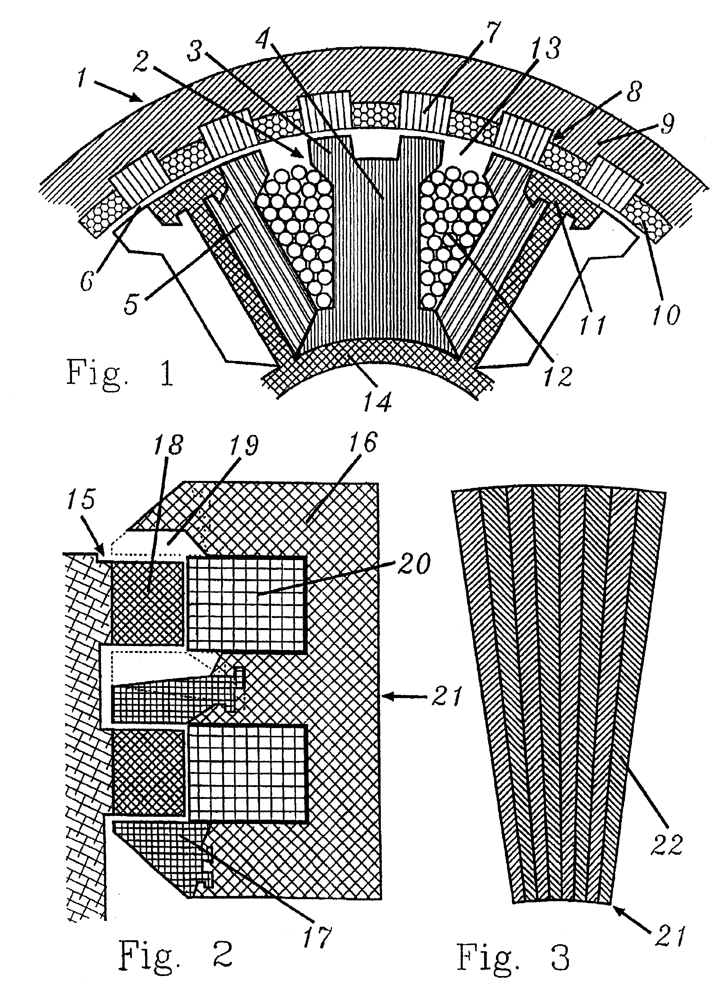
[0032]FIG. 1 shows a cutout from the cross section of a reluctance machine according to invention (1) which consists of six identical magnetic units (2) with four teeth (3) each. In the cutout, only one magnetic unit is shown which consists of a spooled pole segment (4) and two identical non-spooled half pole segments (5). Pole and half pole segments consist of axially stacked grain oriented electric sheet with the preferred direction in radial direction. The half poles have one tooth at the surface of the air gap (6). 24 stator teeth (3) are arranged opposite 26 tooth segments (7) of the rotor (8). The distance between the teeth (3) of adjacent half poles (5) is larger by ⅔ of the tooth width compared to the distance of the teeth within a magnetic unit. The number of teeth per magnetic unit may be 4, 8, 12, 16 etc. (respectively 4×k with k being an integer), and the number of magnetic units may be any multiple of the number of phases.

[0033]So that the rotor teeth (7) do not generat...


PUM


Abstract

Electric machines operating according to the reluctance principle have toothed air gap surfaces between their moving and fixed parts. The magnetizability of these teeth directly affects the performance of the machine. According to the invention, the teeth projecting into the air gap consist of a material which in relation to the remaining soft-magnetic body presents better magnetizability and/or greater magnetic saturation flux density. This material is preferably a grain-oriented electric steel sheet or a cobalt/iron alloy. Alternatively or in addition thereto, the soft-magnetic body in which the conductor coils are positioned can be made entirely of a grain-oriented material by appropriate segmentation. In this case, every other pole is non-spooled and consists of two halves separated by a non-magnetic holding element. The use of steel sheets rolled at an angle also contributes to the improved utilization of space and material in rotating machines, especially in transverse flux machines. The characteristics of the construction provided for in the invention result in the production of little cutting waste and thus raise the performance of electric machines with soft-magnetic teeth at the air gap surface and reduce losses.

Description

[0001]This is a continuation of International Application PCT / DE98 / 01826, with an international filing date of Jul. 2, 1998, and with priority of the German application 197 28 172.9, filed on Jul. 2, 1997, now abandoned.BACKGROUND OF THE INVENTION[0002]1. Field of the Invention[0003]The invention concerns an electric machine with soft magnetic teeth at the air gap surface and a production process for such a machine.[0004]2. Description of Prior Art[0005]Electric machines with soft magnetic teeth at the air gap surface are known in a diversity of designs under the name of “step motor” or “switched reluctance machine”. The toothing causes the magnetic resistance of the magnetic flux, which flows through the air gap, to change as the rotor is moving. The utilizable forces depend on the tooth geometry, the magnetizability of the soft magnetic material, and the flux density in the air gap.[0006]One design which is distinguished by its simple winding technique is the transversal flux mach...

Claims


Application Information

Patent Timeline
Patent Type & Authority Patents(United States)
IPC IPC(8): H02K1/06H02K1/00H02K1/14H02K3/00H02K37/00H02K19/10H02K19/02H02K1/18H02K3/18H02K15/02H02K37/06
CPCH02K1/06H02K1/145H02K1/148H02K19/103H02K15/02
Inventor HILL, WOLFGANG
Owner HILL WOLFGANG
Why Eureka
Try Eureka