Apparatus for Resonant Converters

a resonant converter and apparatus technology, applied in the field of resonant converters, can solve the problems of increasing power loss, reducing the total efficiency, and increasing the current stress on the side, so as to improve the current limit of a resonant converter and reduce the current stress

Active Publication Date: 2013-10-10
HUAWEI DIGITAL POWER TECH CO LTD
View PDF8 Cites 81 Cited by
  • Summary
  • Abstract
  • Description
  • Claims
  • Application Information

AI Technical Summary

Benefits of technology

[0013]These and other problems are generally solved or circumvented, and technical advantages are generally achieved, by preferred embodiments of the present invention which provide an apparatus for resonant converters. In particular embodiments, a multiple constant gain converter discloses an effective power topology to reduce the current stress and improve the current limit of a resonant converter.
[0021]An advantage of an embodiment of the present invention is that a resonant tank of a multiple constant gain converter helps to reduce the current stress and improve the current limit of a resonant converter. As a result, the resonant tank of the multiple constant gain converter helps to improve the efficiency, reliability and cost of the resonant converter.

Problems solved by technology

However, as the switching frequency of full bridge converters increases, the total efficiency is reduced due to extra switching losses in response to a higher switching frequency.
However, the primary side may have a large amount of current stress due to the primary side switches' longer conduction time of the primary current having an amplitude close to the peak current during a freewheeling period, and the reverse recovery of second switches' body diodes may cause further power losses.

Method used


Image

  • Apparatus for Resonant Converters
  • Apparatus for Resonant Converters
  • Apparatus for Resonant Converters

Examples


Embodiment Construction

[0042]The making and using of the presently preferred embodiments are discussed in detail below. It should be appreciated, however, that the present invention provides many applicable inventive concepts that can be embodied in a wide variety of specific contexts. The specific embodiments discussed are merely illustrative of specific ways to make and use the invention, and do not limit the scope of the invention.

[0043]The present invention will be described with respect to preferred embodiments in a specific context, namely a multiple constant gain resonant converter used as a bus converter. The invention may also be applied, however, to a variety of power conversion applications. Hereinafter, various embodiments will be explained in detail with reference to the accompanying drawings.

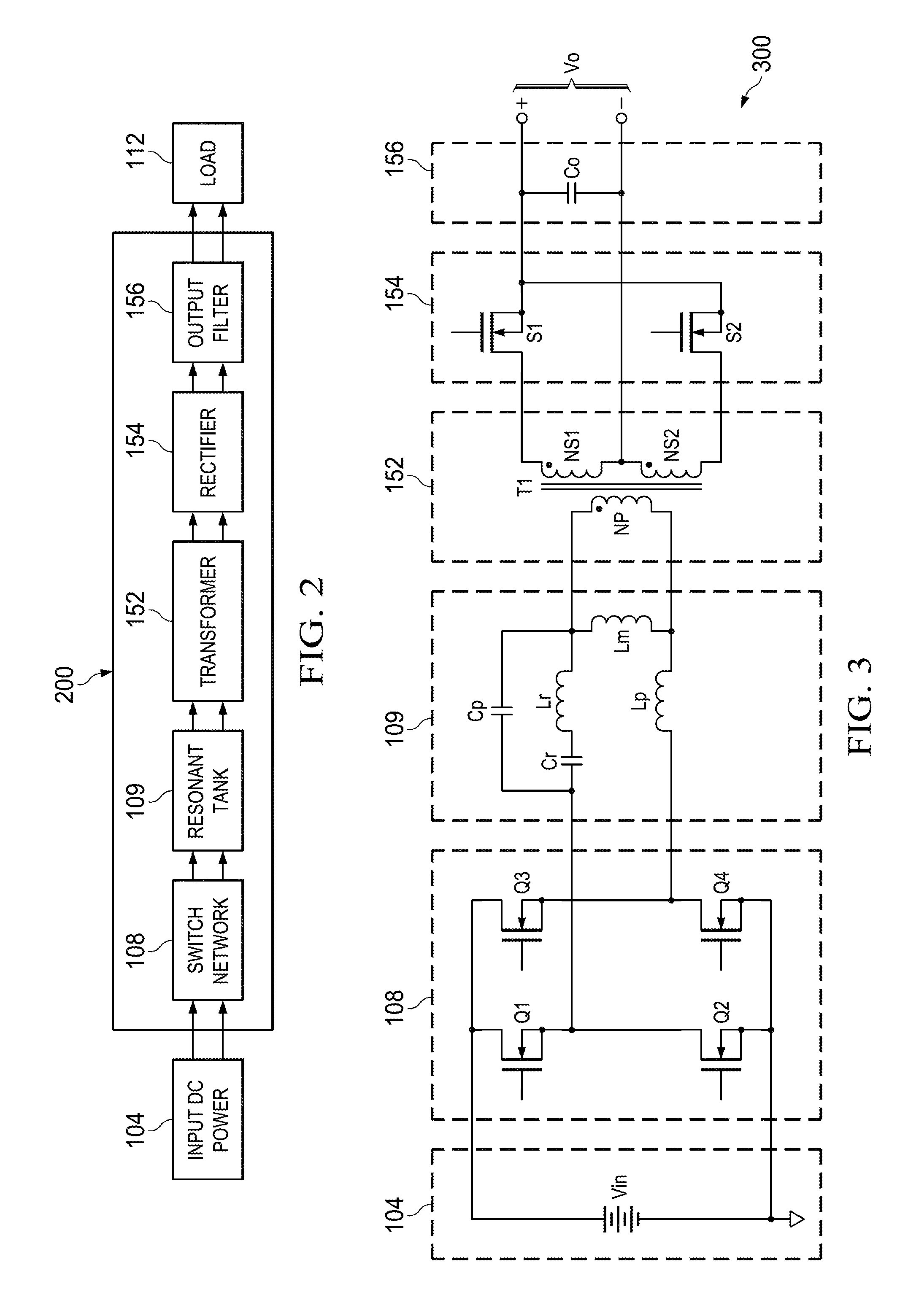
[0044]FIG. 2 illustrates a block diagram of a multiple constant gain resonant converter in accordance with various embodiments of the present disclosure. The multiple constant gain resonant converter 200...


PUM


Abstract

A converter comprises a bridge and a resonant tank coupled between the bridge and an isolation transformer. The converter is configured such that the converter operates at a first constant-gain resonant frequency during a normal operation condition wherein a voltage gain of the converter is essentially insensitive to an output load change and the converter operates at a minimum-gain damping frequency during an abnormal operation condition wherein a voltage gain of the converter is approximately equal to zero.

Description

[0001]This application claims the benefit of U.S. Provisional Application No. 61 / 620,876, filed on Apr. 5, 2012, entitled “Apparatus for Resonant Converters,” which application is hereby incorporated herein by reference.TECHNICAL FIELD[0002]The present invention relates to a resonant converter, and, in particular embodiments, to a multiple constant gain resonant apparatus for bus converter applications.BACKGROUND[0003]A telecommunication network power system usually includes an AC-DC stage converting the power from the AC utility line to a 48V DC distribution bus and a DC-DC stage converting the 48V DC distribution bus to a plurality of voltage levels for all types of telecommunication loads. Both stages may comprise isolated DC-DC converters. Isolated DC-DC converters can be implemented by using different power topologies, such as flyback converters, forward converters, half bridge converters, full bridge converters and the like.[0004]As known in the art, bridge converters generall...

Claims


Application Information

Patent Timeline
Patent Type & Authority Applications(United States)
IPC IPC(8): H02M3/335
CPCH02M3/33576Y02B70/1491H02M2001/0058Y02B70/1433H02M1/0058Y02B70/10
Inventor FU, DIANBOMAO, HENGCHUNDAI, HEPING
Owner HUAWEI DIGITAL POWER TECH CO LTD
Why Eureka
Try Eureka