Twin driver earphone

a technology of earphones and drivers, applied in the direction of earpiece/earphone attachments, transducer details, electrical transducers, etc., can solve the problems of serious defect in the frequency characteristics of earphones, -resonant state would be created, and the effect of suppressing the sound pressur

Active Publication Date: 2013-10-10
OCHARAKU
View PDF0 Cites 20 Cited by
  • Summary
  • Abstract
  • Description
  • Claims
  • Application Information

AI Technical Summary

Benefits of technology

The present invention relates to a sound-isolating earphone that is designed to be inserted into the external auditory canal. The earphone includes two isolated sound leading pipes with different path lengths, which are used to transfer sound waves generated by two electroacoustic transducers to the external auditory canal. These two sound waves are combined just before a sound outlet near the entrance of the external auditory canal. This design suppresses sound pressure peaks at undesired frequencies and prevents a reduction in sound volume in an entirety of sound ranges. The use of two or more small-diameter electroacoustic transducers is advantageous for sound reproduction in a high-frequency range compared to a case where the large-diameter electroacoustic transducer is used. This earphone provides superior sound pressure sensitivity and increased freedom in layout compared to traditional earphones.

Problems solved by technology

Since the conventional sound-isolating earphone is structured to close off the external auditory canal, however, the state of resonance within the external auditory canal varies, causing a deviation of resonant frequency, between points in time before and after the earphone is fitted, and producing a serious defect with respect to frequency characteristics of the earphone.
For this reason, sound components at around 6 kHz are emphasized in the both-end closed pipe resonance mode when the sound-isolating earphone is fitted and, therefore, there has been a problem that a quasi-resonant state would be created, producing a buzzing echo sound.

Method used


Image

  • Twin driver earphone
  • Twin driver earphone
  • Twin driver earphone

Examples


first embodiment

[0045]FIG. 4 is a diagram of a sound-isolating earphone (twin-driver earphone) provided with two independent electroacoustic transducers and sound leading pipes, wherein FIG. 4(a) is a schematic view and FIG. 4(b) is a cross-sectional view.

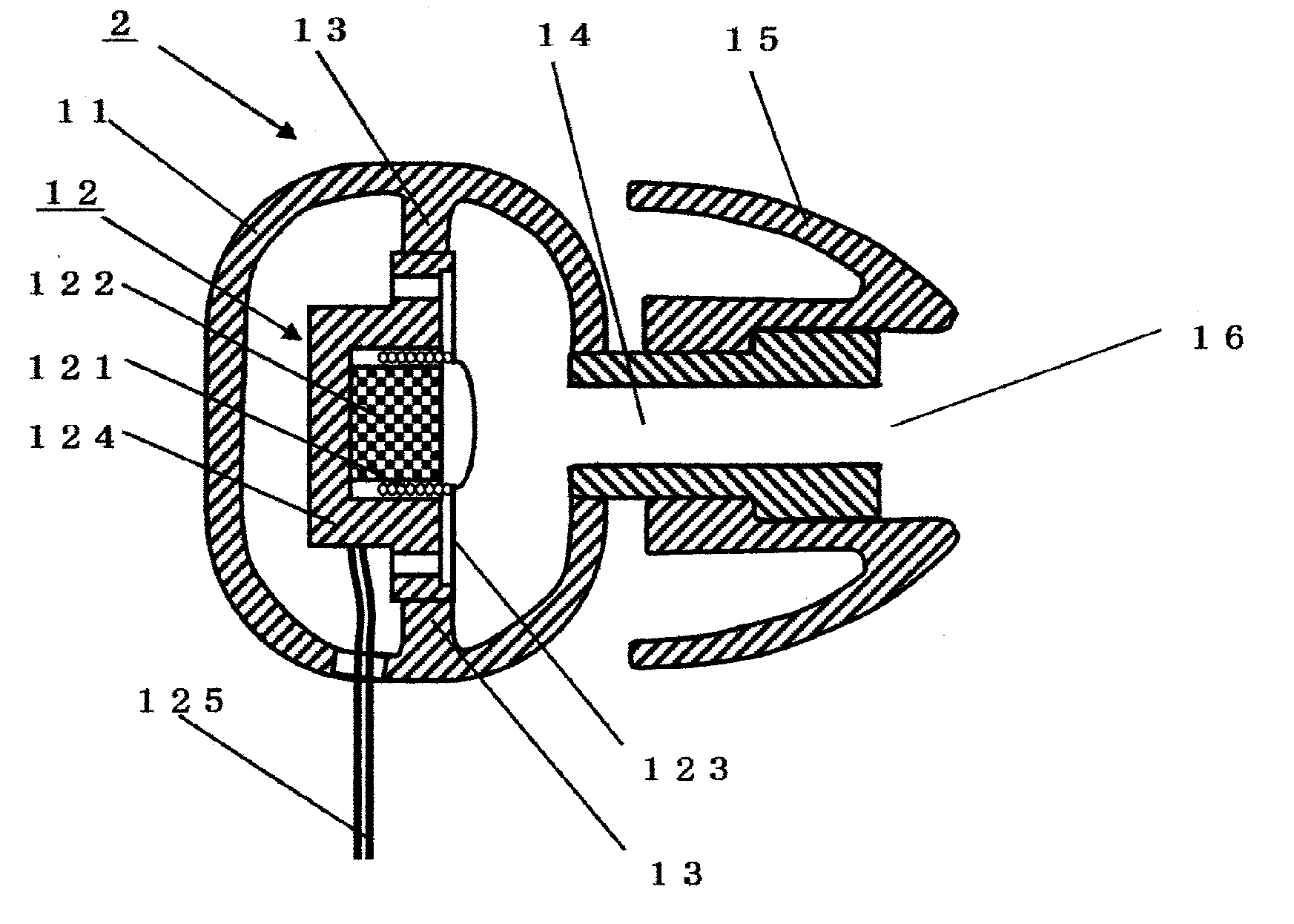
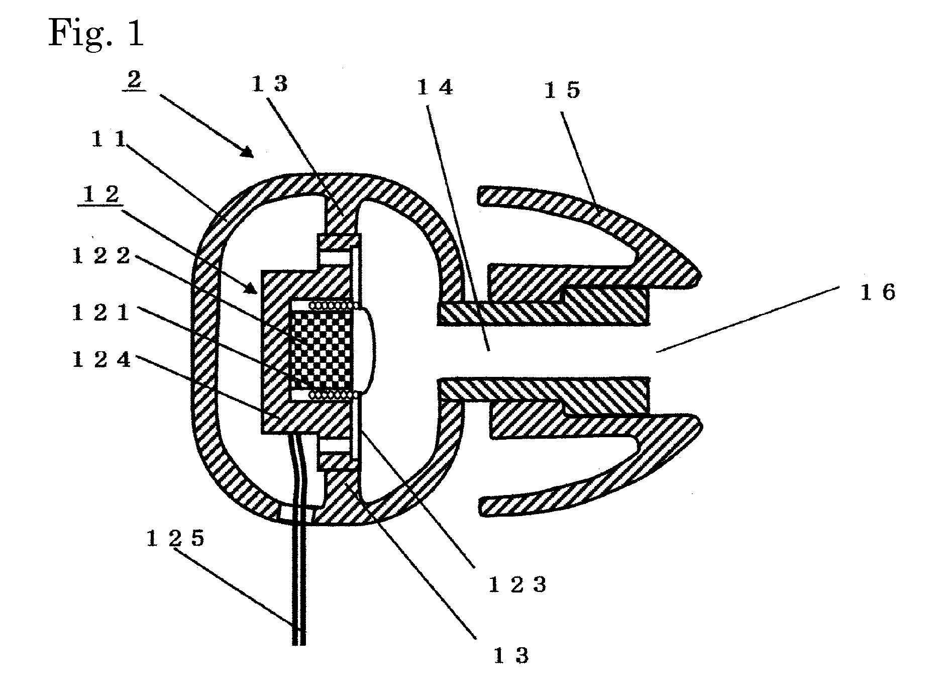
[0046]One housing of the sound-isolating earphone (twin-driver earphone) has the same internal structure as that of the ordinary sound-isolating earphone illustrated in FIG. 1. The sound-isolating earphone (twin-driver earphone) 1 is configured as illustrated in FIG. 4(b), including a first electroacoustic transducer 12a built in a first housing 11a associated with a first sound leading pipe 14a, a second electroacoustic transducer 12b built in a second housing 11b associated with a second sound leading pipe 14b, an ear pad 15, and a lead wire 125 which connects the two electroacoustic transducers 12a, 12b to an unillustrated audio amplifier.

[0047]The electroacoustic transducer 12 includes a coil 121, a permanent magnet 122, a diaphragm 123 and a ...

second embodiment

[0074]A second embodiment is described with reference to FIG. 7. FIG. 7 is a cross-sectional diagram of a sound-isolating earphone provided with two electroacoustic transducers which are disposed in opposite directions. The Figure depicts an example in which two electroacoustic transducers 12 are arranged back to back in a single housing 11. The foregoing discussion of the first embodiment applies also to such an arrangement.

[0075]As depicted in FIG. 7, the two electroacoustic transducers 12a and 12b are arranged in the opposite directions along an arrangement axial line A-A′ which connects central points of respective diaphragms to each other. Here, the arrangement axial line A-A′ is parallel or generally parallel to the direction of a sound wave emitted from a sound outlet 16.

[0076]Although mechanical vibrations produced when the electroacoustic transducers 12 generate sounds become a source of noise (distortion) by moving the diaphragm, it is possible to cancel out the mechanical...

third embodiment

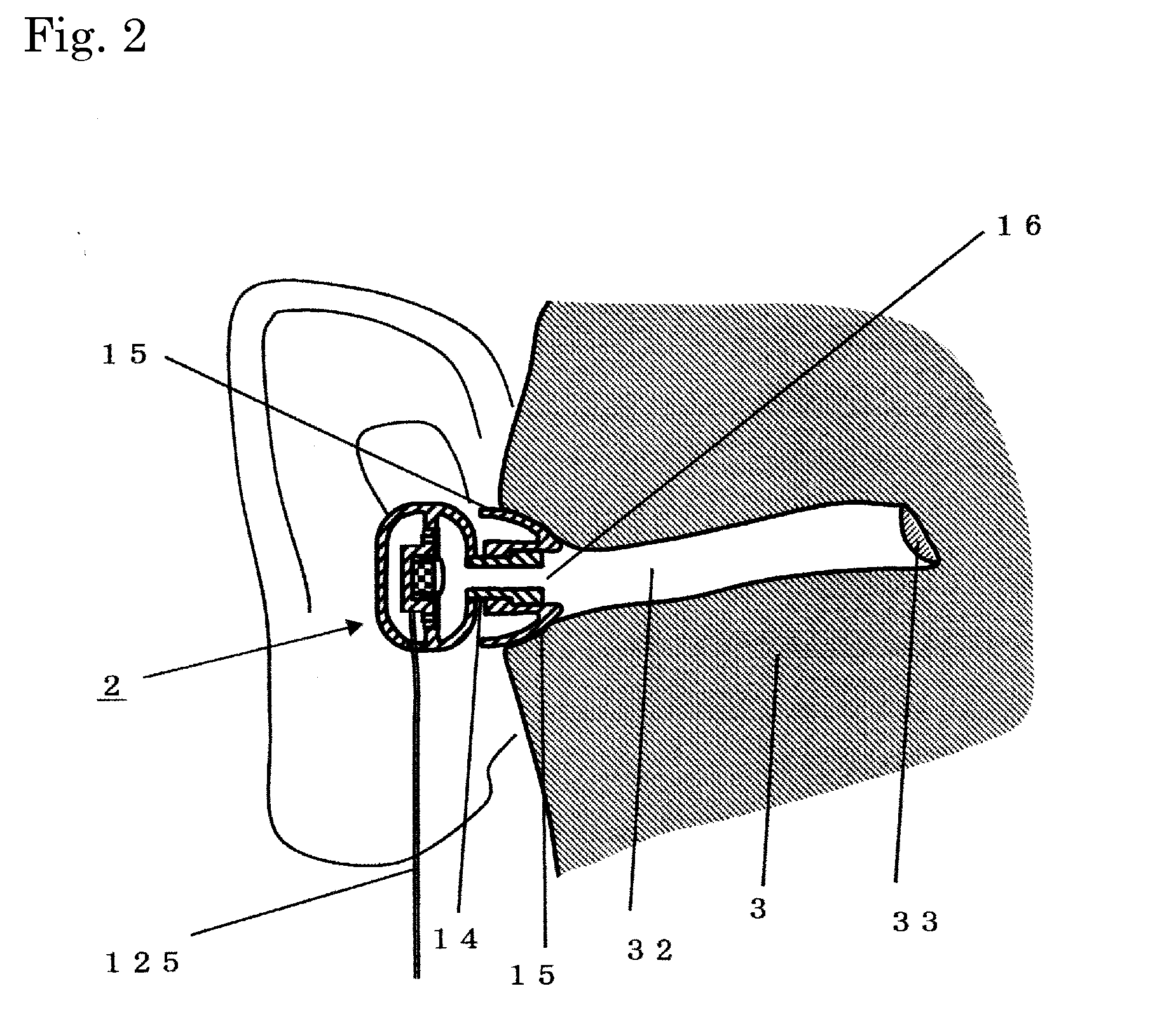
[0080]A third embodiment is a sound-isolating earphone (twin-driver earphone) used with a sound-emitting portion thereof inserted in an entrance of an external auditory canal, the sound-isolating earphone (twin-driver earphone) being characterized by including two or more electroacoustic transducers and sound leading pipes having different path lengths, the sound leading pipes being associated with the respective electroacoustic transducers, wherein sound waves generated by the two or more electroacoustic transducers at the same phase and passed through the respective sound leading pipes are combined at the entrance of the external auditory canal, the sound pressure of a frequency component of which half the wavelength equals a difference among path lengths of the two or more sound leading pipes is suppressed, and an acoustic resistor is disposed in each sound-conducting path of all or part of the two or more sound leading pipes.

[0081]The third embodiment is described with reference...


PUM


Abstract

Provided is a technique for improving frequency characteristics by an acoustics-related method so that a sound is heard with natural frequency characteristics when a sound-isolating earphone is fitted in a human ear. A sound-isolating earphone is provided with two or more electroacoustic transducers, wherein independently generated sound waves are passed through isolated sound leading pipes and are mixed just before an entrance of an external auditory canal, and a sound wave of which is twice the difference between path lengths of the two sound leading pipes is attenuated. This serves to provide an easy-to-hear improved sound quality by suppressing the sound wave at around 6 kHz that is transmitted with characteristically high intensity in a sound-isolating earphone.

Description

TECHNICAL FIELD[0001]The present invention relates to a sound-isolating earphone which is used with a sound-emitting portion thereof inserted in an entrance of an external auditory canal.BACKGROUND ART[0002]An ordinary sound-isolating earphone is configured as illustrated in FIG. 1, including an electroacoustic transducer 12 disposed inside a housing 11, a lead wire 125 which connects the electroacoustic transducer 12 to an external amplifier, for instance, a sound leading pipe 14 which transmits a sound wave generated by the electroacoustic transducer 12 to the external auditory canal, and an ear pad 15 which serves as a cushion when the earphone is inserted into the external auditory canal and also shuts off external noise.[0003]The ear pad 15 having a sound outlet 16 at an extreme end of a portion inserted in the external auditory canal is made of soft plastic, rubber, or the like, having elasticity and fits in close contact with an inside wall of the external auditory canal with...

Claims


Application Information

Patent Timeline
IPC IPC(8): H04R1/22
CPCH04R1/22H04R1/227H04R1/2857H04R1/1016H04R1/2849H04R1/2873
Inventor YAMAGISHI, MAKOTO
Owner OCHARAKU
Why Eureka
Try Eureka