
Micromechanical coriolis rate of rotation sensor

a technology of rotation sensor and micromechanical coriolis, which is applied in the direction of mechanical instruments, turn-sensitive devices, instruments, etc., can solve the problems of sensor damage, sensor relatively sensitive to external force influences, and even damage to the sensor, so as to prevent false measurements

Active Publication Date: 2013-10-17
HANKING ELECTRONICS LTD
View PDF6 Cites 11 Cited by
  • Summary
  • Abstract
  • Description
  • Claims
  • Application Information

AI Technical Summary

Benefits of technology

The present invention relates to a rate of rotation sensor that is largely shock-resistant and not sensitive to external influences. The sensor detects shock effects to prevent false measurements. The connecting elements ensure system stability by reducing sensitivity to shock conditions on the rate of rotation sensor. The driving masses mutually affect each other in case of a deflection about the Y-axis, thus significantly reducing sensitivity with respect to shock conditions on the rate of rotation sensor. The connecting element can be attached at the outermost end of the driving mass or between the two driving masses. Various stoppers can be provided to prevent damage to the individual displaced parts.

Problems solved by technology

A disadvantage of the rate of rotation sensors according to the state of the art is that said sensors are relatively sensitive to such external force influences.
Imprecise measurements are thereby obtained, or the sensor can even be damaged.

Method used


Image

  • Micromechanical coriolis rate of rotation sensor
  • Micromechanical coriolis rate of rotation sensor
  • Micromechanical coriolis rate of rotation sensor

Examples


Embodiment Construction

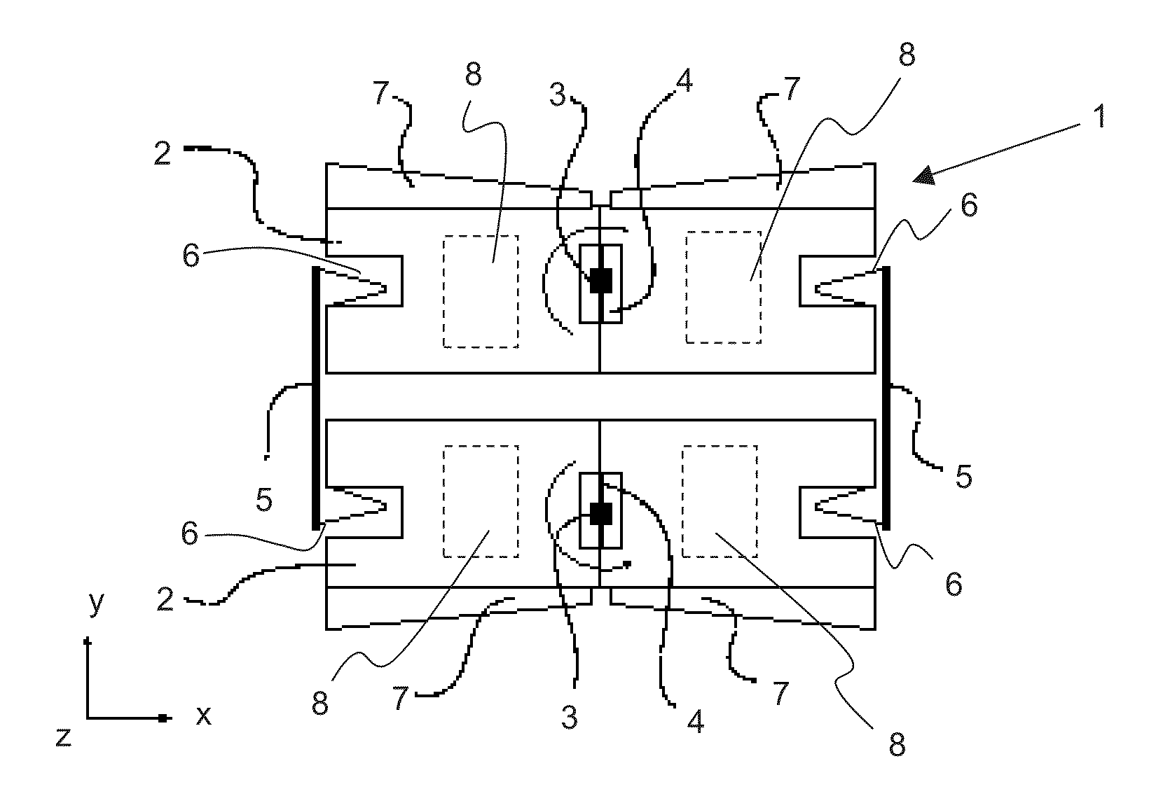
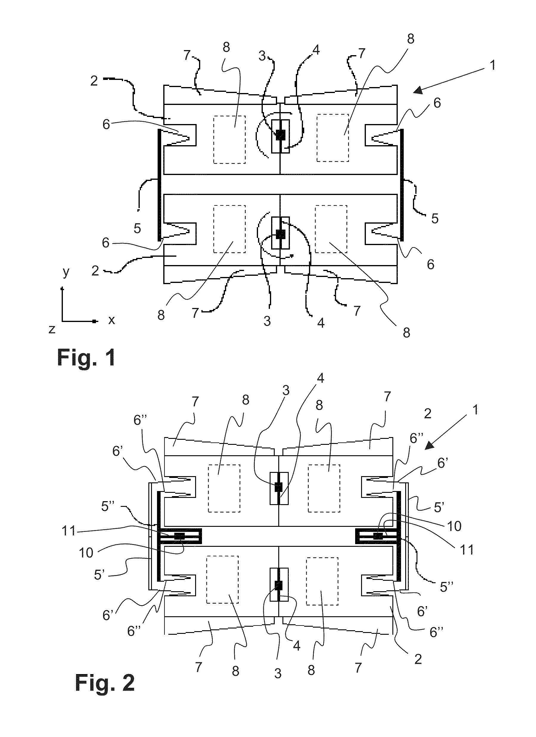
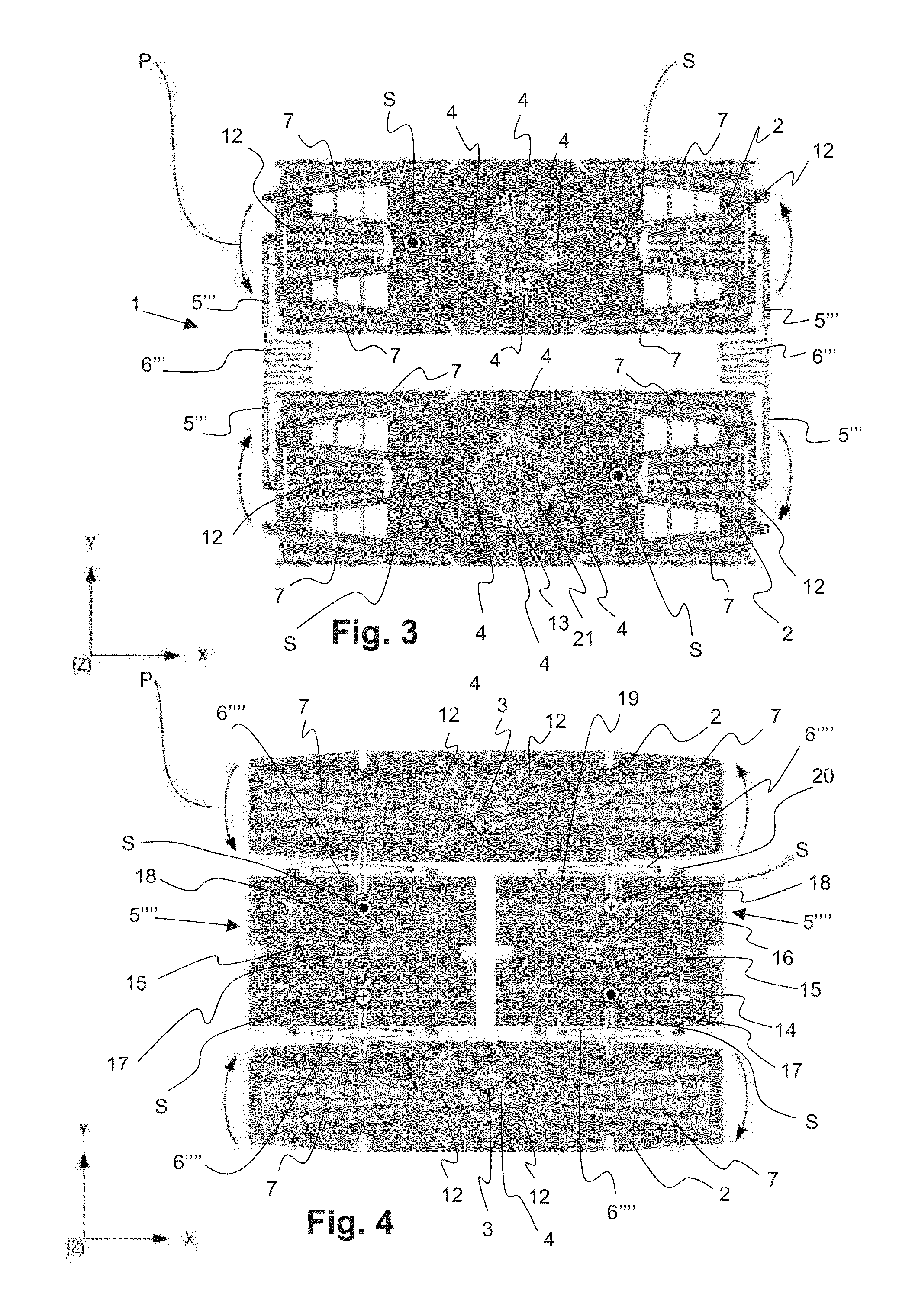
[0031]The embodiment of FIG. 1 shows a sketch of a plan view of a micromechanical Coriolis rate of rotation sensor 1 according to the invention having two driving masses 2. The driving masses 2 are disposed parallel to a substrate, not shown here, located within the plane of the drawing. The driving masses 2 are each connected to the substrate by means of an anchor 3 and anchor springs 4 disposed thereon. The anchor springs 4 allow rotation about a Z-axis in an orthogonal coordinate system. In said coordinate system, the Z-axis protrudes out of the plane of the drawing, while the X-axis is disposed in the longitudinal direction of the driving masses 2 and the Y-axis is disposed in the transverse direction of the driving masses 2. The X-axis is thereby the measurement axis, meaning that the rate of rotation sensor is able to determine a rotation of the sensor or the substrate about the X-axis. The Y-axis disposed orthogonal thereto and in the same plan represents the detection axis. ...


PUM


Abstract

A micromechanical Coriolis rate of rotation sensor for detecting a rate of rotation, comprising a substrate, a measurement axis (X-axis), a detection axis (Y-axis), and a drive axis (Z-axis), each disposed orthogonally to each other and a first and a second driving mass (2) disposed in an X-Y plane parallel to the substrate. Each driving mass (2) being rotatably connected to the substrate by means of a central suspension. The two central suspensions being disposed along the Y-axis. Drive means are used for generating a rotational oscillation of the driving masses (2) about the drive axis (Z) at each central suspension. At least one elastic connecting element (5) is disposed on each of the driving masses (2) on both sides of the Y-axis and spaced apart from the same for connecting and oscillating the two driving masses (2) in a mutually tuned manner.

Description

CROSS REFERENCE TO RELATED APPLICATIONS[0001]The application claims the benefit of German Application Serial No. 10 2011 056 971.5, entitled “Mikromechanischer Coriolis-Drehratensensor”, filed on Dec. 23, 2011, the subject matter of which is incorporated herein by reference.BACKGROUND[0002]A. Technical Field[0003]The present invention relates to a micromechanical Coriolis rate of rotation sensor (MEMS rate of rotation sensor) for detecting a rate of rotation, comprising a substrate, a measurement axis (X-axis), a detection axis (Y-axis), and a drive axis (Z-axis), each disposed orthogonally to each other. The rate of rotation sensor further comprises a first and a second driving mass disposed in an X-Y plane parallel to the substrate, wherein each driving mass is rotatably connected to the substrate by means of a central suspension. The two central suspensions are disposed along the Y-axis. Drive means for generating a rotational oscillation of the driving masses about the drive axi...

Claims


Application Information

Patent Timeline
IPC IPC(8): G01C19/04
CPCG01C19/04G01C19/5712Y10T74/1293G01C19/56G01C19/5621G01C19/5719G01C19/5747
Inventor ROCCHI, ALESSANDROMARCHETTI, ELEONORABERTINI, LORENZO
Owner HANKING ELECTRONICS LTD
Learn More