Fuel vapor treating apparatus

a technology of vapor treatment and vapor treatment, which is applied in the direction of separation processes, transportation and packaging, propulsion parts, etc., can solve the problems of blocked circulation path, achieve improved sealing capability, reduce pressure loss, and improve ease of refueling

Active Publication Date: 2013-10-17
AISAN IND CO LTD
View PDF8 Cites 18 Cited by
  • Summary
  • Abstract
  • Description
  • Claims
  • Application Information

AI Technical Summary

Benefits of technology

[0006]According to this aspect, during refueling, a stream of fuel vapor from the fuel tank flows into the circulation path, and the negative pressure generator generates negative pressure by using the stream and applies the negative pressure on the back pressure chamber of the diaphragm valve. Thus, the diaphragm valve is opened by a combination of the inner pressure of the fuel tank and the negative pressure. As a result, fuel vapor is discharged from the fuel vapor into the adsorbent canister through, the fuel vapor path, so that the fuel vapor is adsorbed in the adsorbent canister. When the fuel tank is filled up, the circulation path is blocked. Thus, the stream of the fuel vapor in the circulation path is stopped, and the negative pressure generator stops generating negative pressure, so that the diaphragm valve is closed. Therefore, because the diaphragm valve is configured to he opened by the combination of the inner pressure of the fuel tank and the negative pressure, pressure loss can be decreased and ease of refueling can he improved compared with a conventional, apparatus where a diaphragm valve is opened by only infernal pressure of a fuel tank. In addition, sealing capability can be improved by increasing opening pressure of the diaphragm valve.

Problems solved by technology

When the fuel tank is filled up, the circulation path is blocked.

Method used


Image

  • Fuel vapor treating apparatus
  • Fuel vapor treating apparatus
  • Fuel vapor treating apparatus

Examples


Embodiment Construction

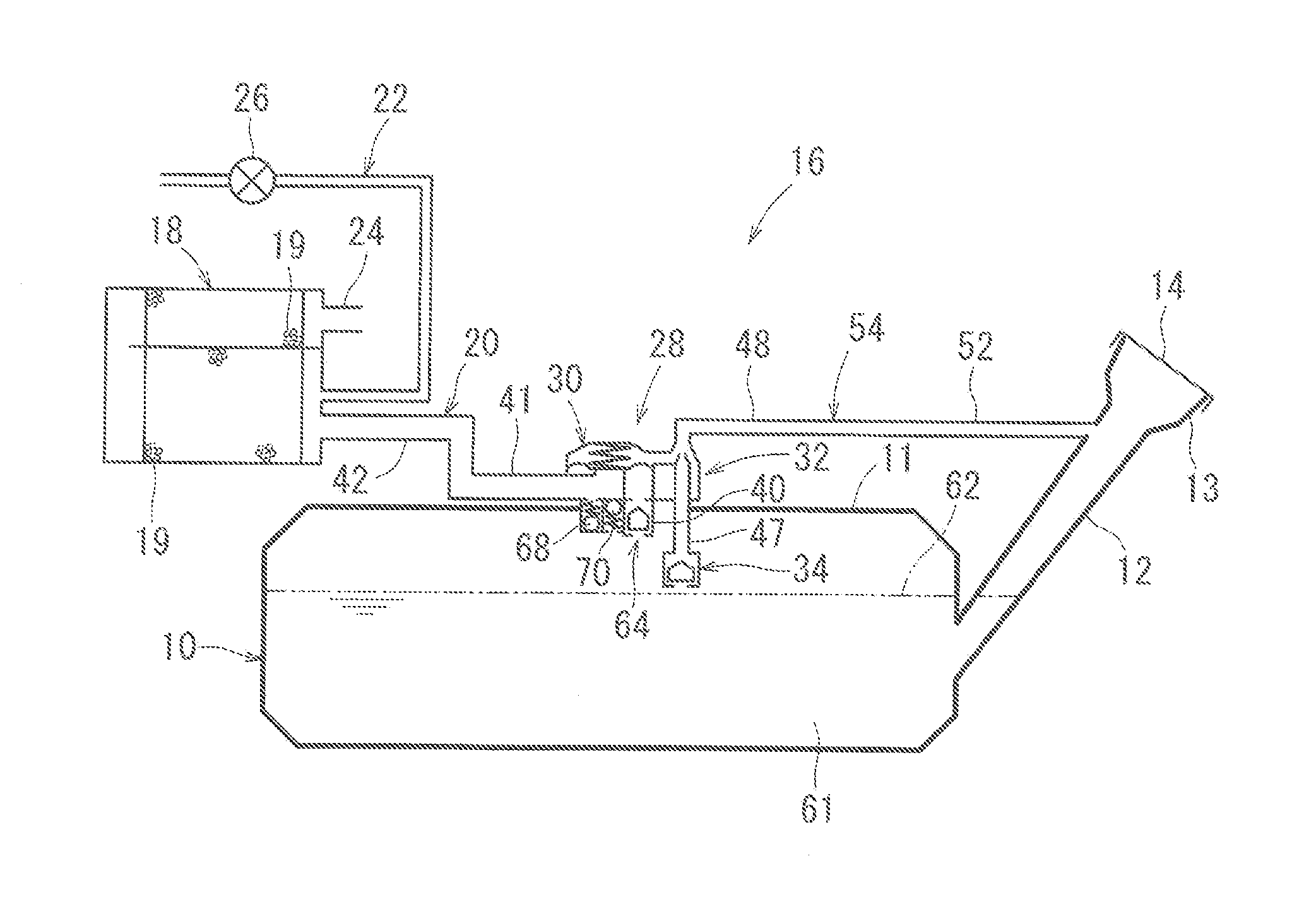
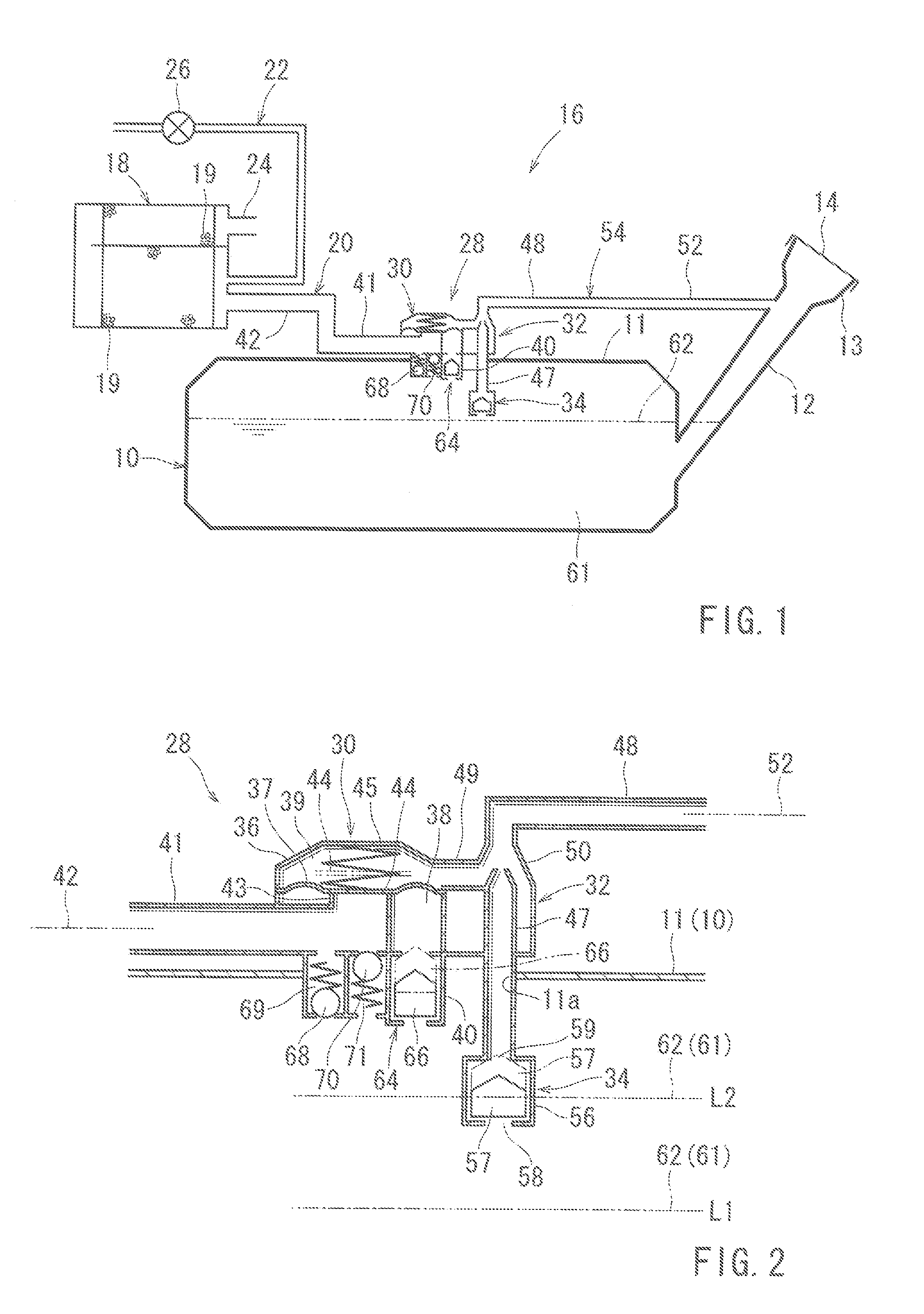
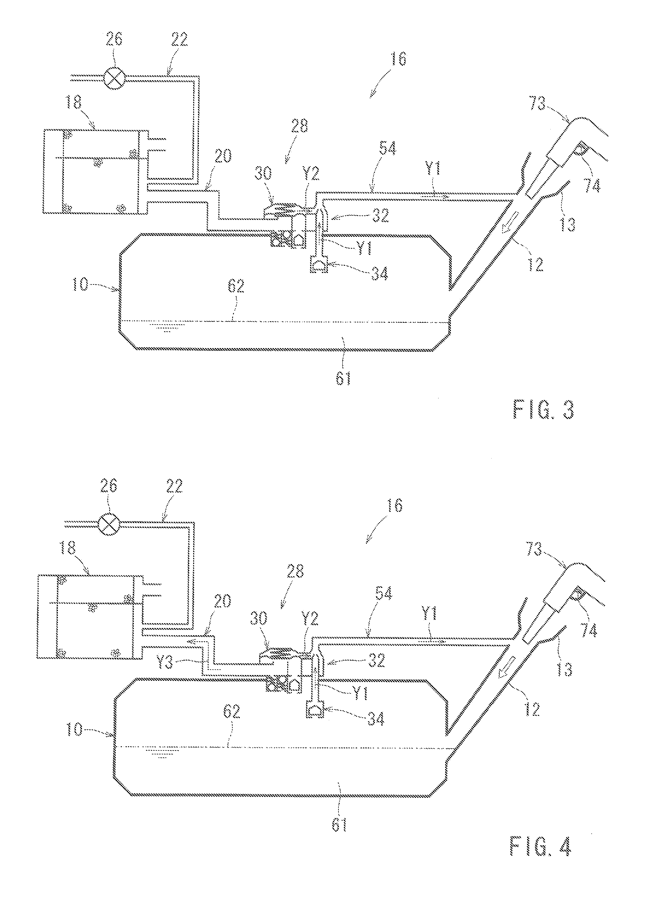
[0014]Each of the additional features and teachings disclosed above and below may be utilized separately or in conjunction with other features and teachings to provide improved fuel vapor treating apparatuses. Representative examples of the present invention, which examples utilized many of these additional features and teachings both separately and in conjunction with one another, will now be described in detail with reference to the attached drawings. This detailed description is merely intended to teach a person of skilled in the art further details for practicing preferred aspects of the present teachings and is not intended to limit the scope of the invention. Only the claims define the scope of the claimed invention. Therefore, combinations of features and steps disclosed in the following detailed description may not be necessary to practice the invention in the broadest sense, and are instead taught merely to particularly describe representative examples of the invention. Mor...


PUM


Abstract

A fuel vapor treating apparatus includes a fuel tank having an inlet pipe and being configured to preserve liquid fuel therein, an adsorbent canister filled with an adsorbent capable of adsorbing fuel vapor, a fuel vapor path connecting the fuel tank to the adsorbent canister, a diaphragm valve having a back pressure chamber and being configured to open and close the fuel vapor path, a circulation path connecting the fuel tank to the inlet pipe for circulating fuel vapor from the fuel tank to the inlet pipe during refueling and being configured to be blocked when, the fuel tank is filled up, and a negative pressure generator connected to the circulation path and the back pressure chamber and configured to generate negative pressure by using a stream of the fuel vapor in the circulation path in order to cause the negative pressure to act on the back pressure chamber of the diaphragm valve.

Description

[0001]This application claims priority to Japanese patent application Ser. No. 2012-090772, the contents of which are incorporated herein by reference.BACKGROUND OF THE INVENTION[0002]This disclosure relates to a fuel vapor treating apparatus generally mounted on a vehicle such as an automobile.[0003]A conventional fuel vapor treating apparatus has an adsorbent canister capable of adsorbing and desorbing fuel vapor from a fuel tank, a fuel vapor path, connecting the adsorbent canister to the fuel tank, and a diaphragm valve configured to close and open the fuel vapor path (for example, Japanese Laid-Open Patent Publication No. 11-208293).[0004]In a conventional fuel vapor treating apparatus, inner pressure of the fuel tank acts on a pressure control chamber in order to open the diaphragm valve during refueling. Then, gas having a content of fuel vapor flows from the fuel tank into the adsorbent canister. In such a configuration, it is difficult to achieve improvements in both (1) ea...

Claims


Application Information

Patent Timeline
Patent Type & Authority Applications(United States)
IPC IPC(8): B01D53/04
CPCB01D53/0446B60K15/03504B60K2015/03289B60K2015/03263B60K2015/03276B60K15/03519B60K2015/03296B60K2015/03514B60K2015/03538
Inventor KIMOTO, JUNYA
Owner AISAN IND CO LTD
Why Eureka
Try Eureka