
Hybrid Electric Vehicle System and Method of Controlling The Same

a hybrid electric vehicle and motor technology, applied in the direction of electric control, electronic commutator, dynamo-electric converter control, etc., can solve the problems of difficult normal motor control, reduced battery capacity, and inability to travel only with the engine, so as to suppress the significant deterioration of the controllability of the motor

Active Publication Date: 2013-10-17
HITACHI ASTEMO LTD
View PDF4 Cites 18 Cited by
  • Summary
  • Abstract
  • Description
  • Claims
  • Application Information

AI Technical Summary

Benefits of technology

The patent aims to prevent significant deterioration of motor control even if there are abnormalities in the resolver or its peripheral circuit. The technical effect is to ensure safe and reliable operation of the motor regardless of such challenges.

Problems solved by technology

However, because the motor control apparatus (inverter) cannot accurately detect the rotation angle or the number of revolutions of the motor when the resolver or a peripheral circuit thereof fails, it is difficult to normally perform the motor control.
Therefore, for a fail safe measure, a method of stopping the motor control and continuing traveling only with the engine is considered, but in this case, because the battery cannot be charged by the motor, a battery capacity is gradually decreased, and as a result, the traveling only with the engine becomes impossible such that the vehicle stops.

Method used


Image

  • Hybrid Electric Vehicle System and Method of Controlling The Same
  • Hybrid Electric Vehicle System and Method of Controlling The Same
  • Hybrid Electric Vehicle System and Method of Controlling The Same

Examples


Embodiment Construction

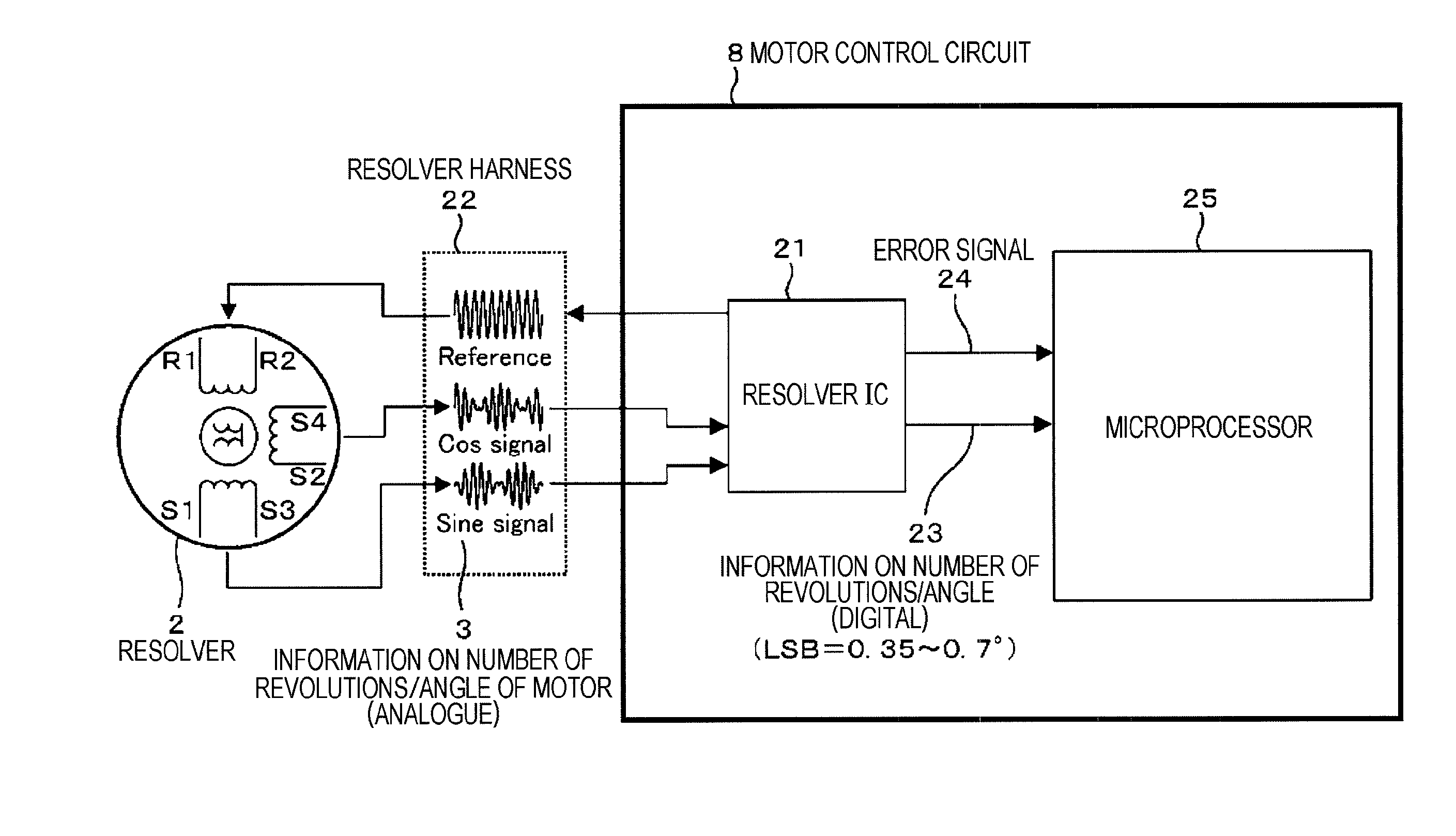
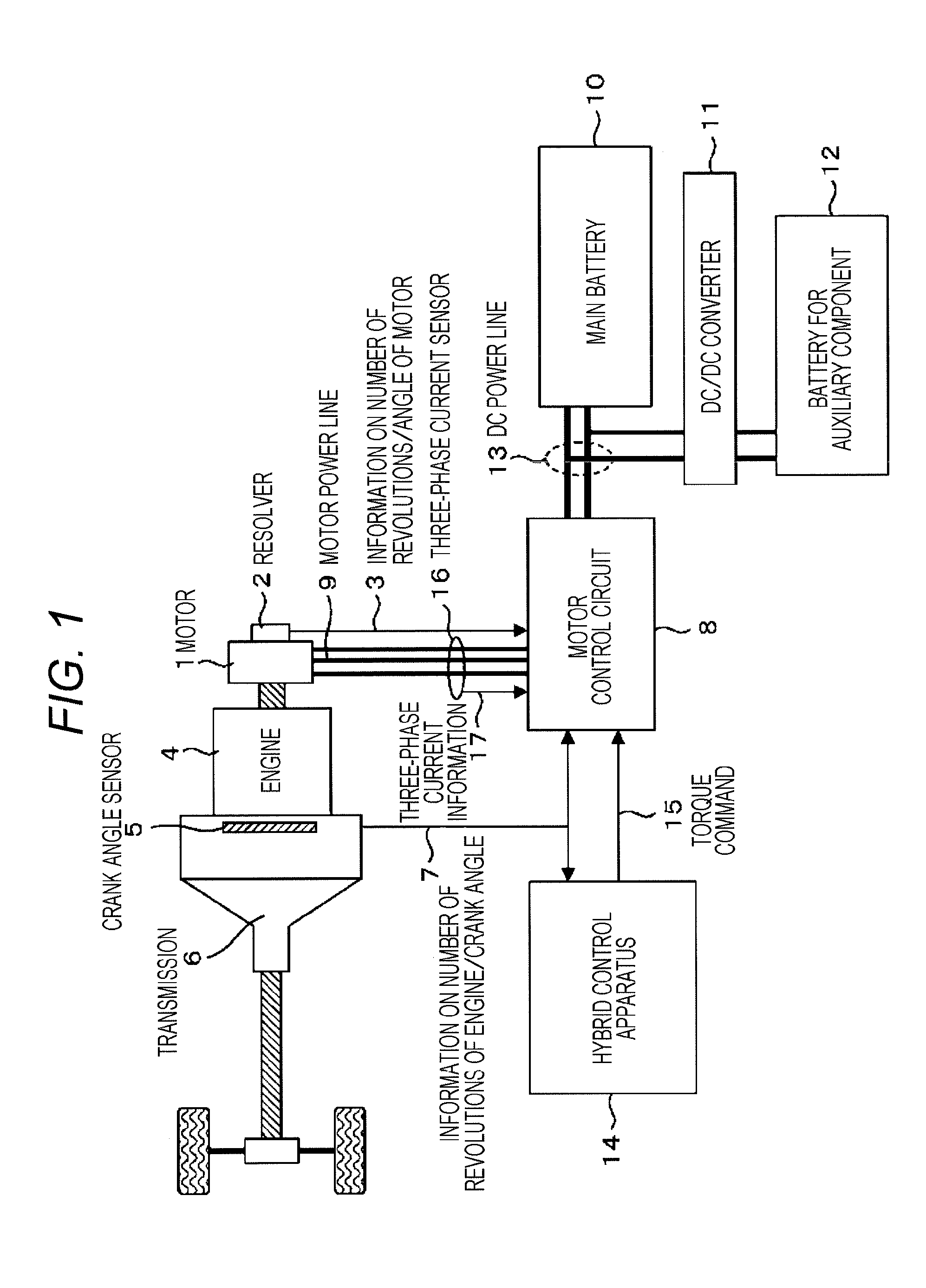
[0029]FIG. 1 is a configuration diagram of a system of a hybrid vehicle that is an example of an embodiment. As illustrated in FIG. 1, a system of a hybrid vehicle includes a motor 1 for driving a vehicle, a resolver 2 which detects the number of revolutions and a rotation angle of the motor 1, an engine 4 connected to the motor 1 through a crankshaft, a crank angle sensor 5 which detects the number of revolutions and a rotation angle of the crankshaft of the engine 4, a transmission 6 which transmits a rotational force of the crankshaft to an axle, a hybrid control apparatus 14 which controls the entire vehicle, a motor control circuit 8, a three-phase current sensor 16, a main battery 10, a DC / DC converter 11, and a battery 12 for an auxiliary component.

[0030]The main battery 10 is a high voltage battery to drive the motor 1, and is a secondary battery formed of lithium ion, nickel hydride or the like.

[0031]The battery 12 for an auxiliary component is a low voltage battery that dr...


PUM


Abstract

The present invention is directed to a method of estimating a motor rotation angle that does not affect precision of a detected angle of a crank angle sensor, which is an alternative sensor, when abnormality occurs in a resolver and a peripheral circuit, and performing a motor control without failure of an inverter or peripheral device. A vehicle system includes a motor, a resolver detecting a rotor rotation angle of the motor, a motor control circuit controlling the motor based on information on rotor rotation angle and torque command value, an engine connected to the motor through a crankshaft, and a crankshaft sensor detecting revolutions of the crankshaft, in which the motor control circuit estimates rotor rotation angle based on a variation rate of the number of revolutions of the crankshaft when abnormality of the resolver is detected, and performs a weak field control based on estimated rotor rotation angle.

Description

TECHNICAL FIELD[0001]The present invention relates to a method of controlling a motor mounted in an electric vehicle such as a hybrid electric vehicle.BACKGROUND ART[0002]A hybrid electric vehicle is a vehicle including a motor in addition to an engine in the related art as a travel driving source, traveling only with the motor being driven or driving the motor to start or assist the engine, or performing regeneration (generation) to charge a battery.[0003]In order to detect a rotation angle and the number of revolutions of the motor, a rotation angle sensor such as a resolver is attached to the motor, and a motor control apparatus (inverter) performs motor control most efficiently based on information on the rotation angle or the number of revolutions from the resolver.[0004]However, because the motor control apparatus (inverter) cannot accurately detect the rotation angle or the number of revolutions of the motor when the resolver or a peripheral circuit thereof fails, it is diffi...

Claims


Application Information

Patent Timeline
Patent Type & Authority Applications(United States)
IPC IPC(8): H02P27/06B60L50/16
CPCH02P27/06B60W10/08B60W20/00B60W50/029B60W2510/0638B60W2710/081B60W2710/083F02D41/009B60L3/0038B60L15/025B60L15/20B60L2240/421B60L2240/441Y02T10/64Y02T10/72B60W20/50
Inventor GOTO, KOSEIOISHI, YUKIHIKO
Owner HITACHI ASTEMO LTD
Learn More