Light emitting device attached to image pickup apparatus

a technology of light emitting device and image pickup, which is applied in the direction of lighting and heating apparatus, lighting elements, instruments, etc., can solve the problems of communication error, small space for battery housing parts, and difficult to reduce the size of battery housing parts, so as to achieve high multifunctionality, reduce size, and high space efficiency

Active Publication Date: 2013-10-17
CANON KK
View PDF2 Cites 1 Cited by
  • Summary
  • Abstract
  • Description
  • Claims
  • Application Information

AI Technical Summary

Benefits of technology

[0011]The present invention provides a mechanism that makes it possible to arrange electrical components and a circuit board, with high space efficiency, such that a malfunction caused by noise from a light emission section can be reduced, to thereby achieve size reduction and high multifunctionality of the light emitting device.

Problems solved by technology

On the other hand, it is becoming an important challenge to space-efficiently arrange electrical components and the circuit board, due to a demand for size reduction.
By the way, in a flash device, due to a demand for further size reduction and multifunctionality, space for a battery housing part the size of which is difficult to be reduced is relatively increased, but due to an increase in the number of electrical components and components of a circuit board for multifunctionality, space for housing these components becomes very small.
For this reason, in accordance with reduction of the size of the flash device, noise from a light emission section is apt to enter the communication line of a control IC, causing a communication error.
The communication error is apt to lead to e.g. a malfunction in which an appropriate amount of light cannot be emitted.
For this reason, the control IC is likely to be affected by noise from the light emission section during flash light emission, which is apt to cause a malfunction in which an appropriate amount of light cannot be emitted.
For this reason, in accordance with the further multifunctionality of the flash device, space for housing the circuit boards and the dedicated connection members is increased, which causes an increase in the size of the flash device, and the additional provision of the dedicated connection members causes an increase in the manufacturing costs of the flash device.

Method used


Image

  • Light emitting device attached to image pickup apparatus
  • Light emitting device attached to image pickup apparatus
  • Light emitting device attached to image pickup apparatus

Examples


Embodiment Construction

[0037]The present invention will now be described in detail below with reference to the accompanying drawings showing embodiments thereof.

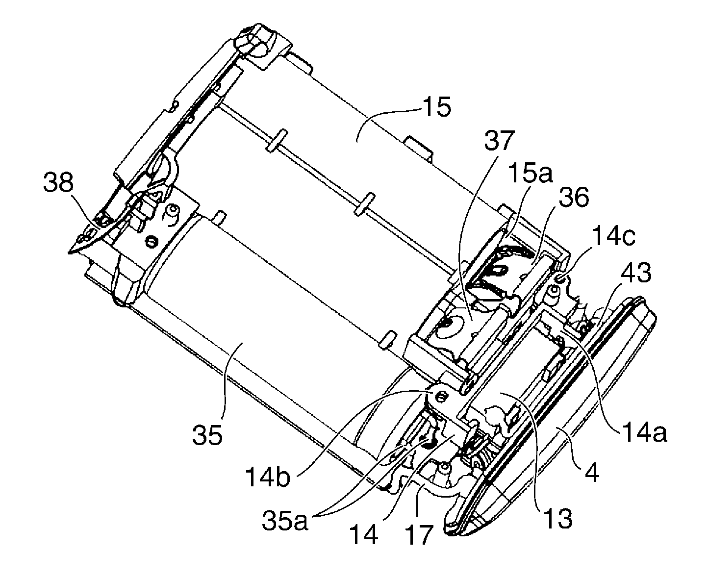
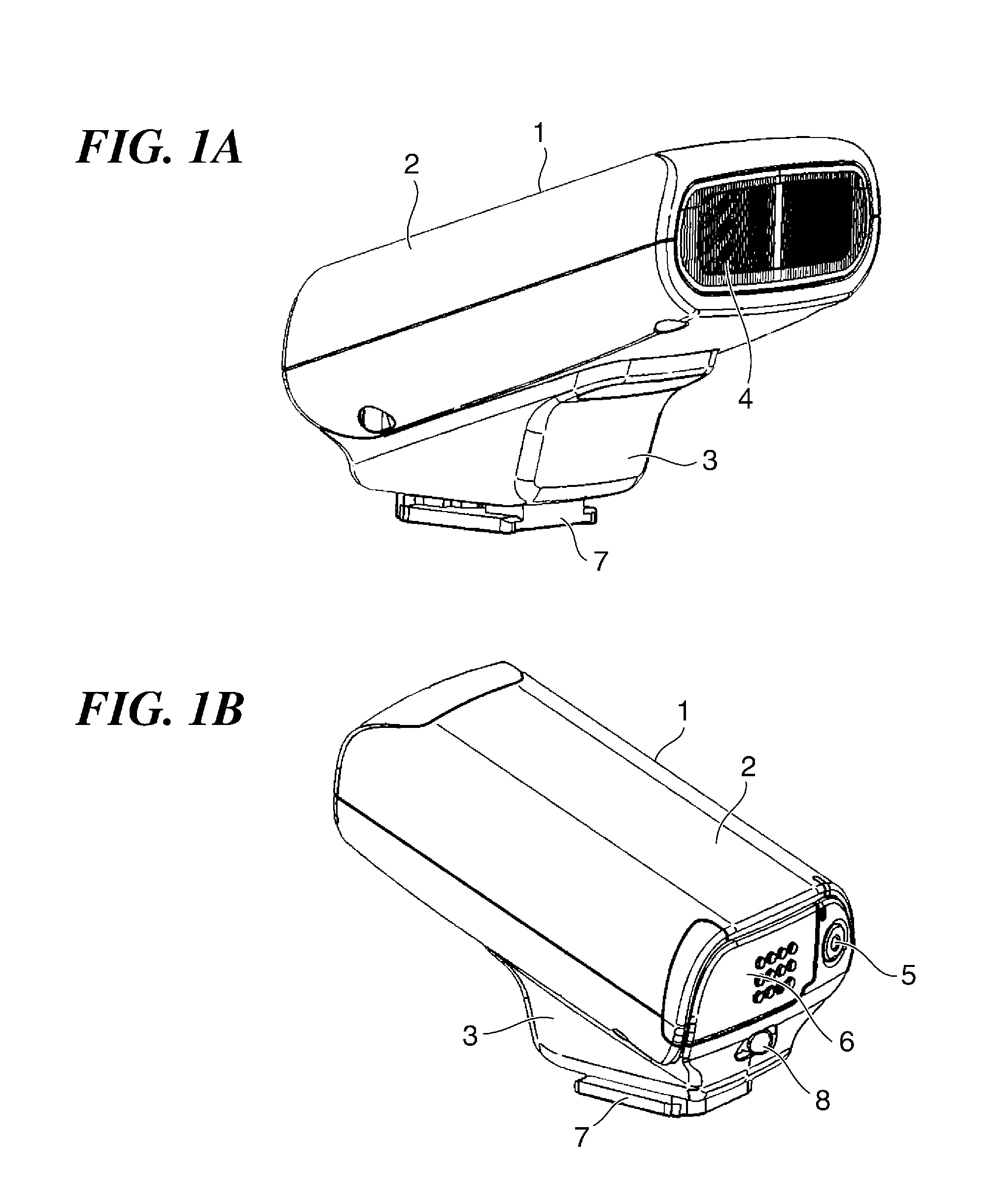
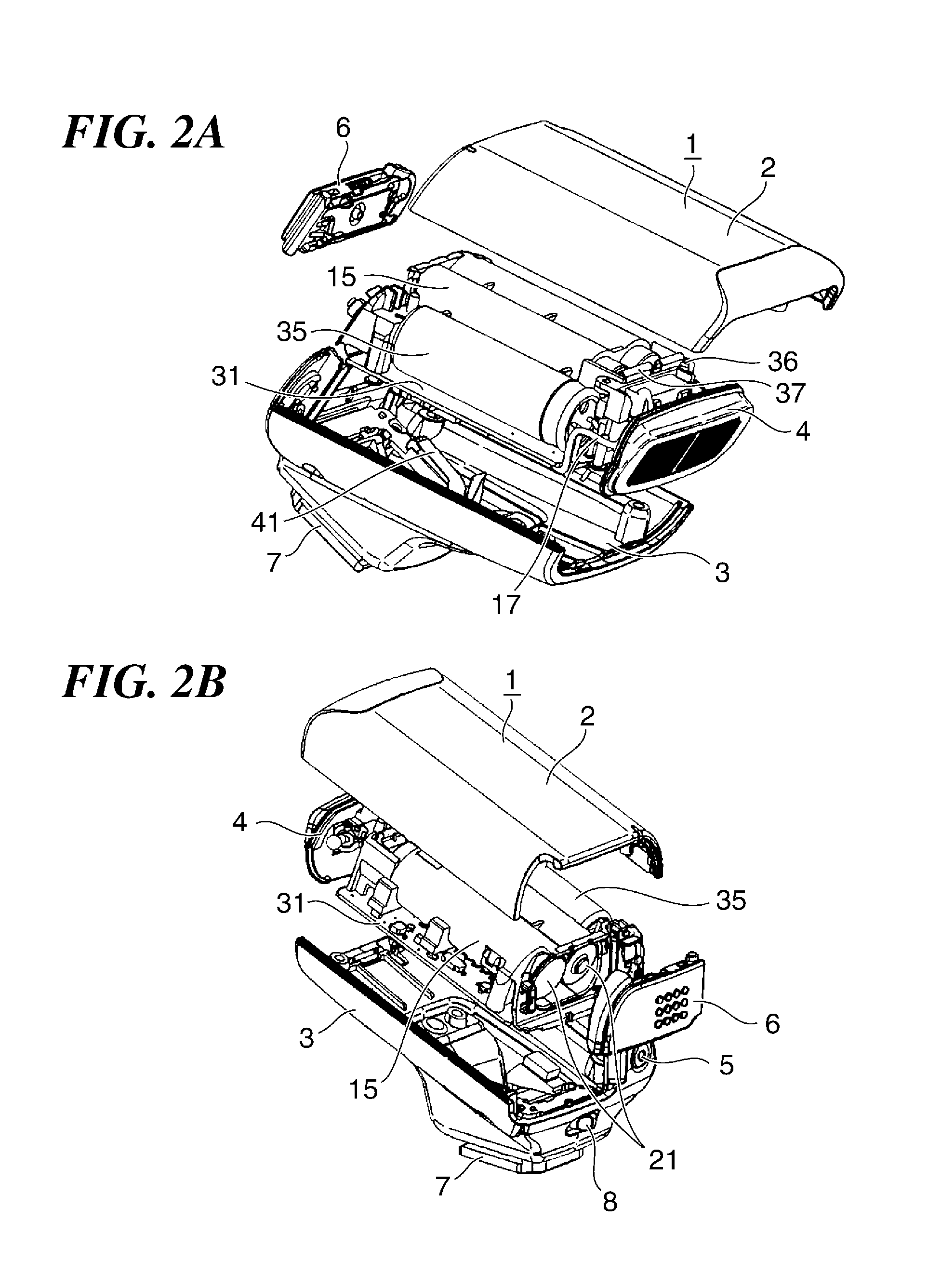
[0038]FIG. 1A is a perspective view of the appearance of a flash device as a light emitting device according to a first embodiment of the present invention, and FIG. 1B is a perspective view of the appearance of the flash device in FIG. 1A, as viewed from the rear of the same. FIG. 2A is an exploded perspective view of FIG. 1A, and FIG. 2B is an exploded perspective view of FIG. 1B. Note that in the present embodiment, the flash device is detachably attached to an external apparatus, such as a digital camera or the like image pickup apparatus, or a communication apparatus.

[0039]As shown in FIGS. 1A and 1B and FIGS. 2A and 2B, the flash device of the present embodiment comprises a device body 1 and a leg part 7 mounted to the bottom of the device body 1. The leg part 7 is detachable from a connection part of an external apparatus, such as a camera-...


PUM


Abstract

A mechanism which makes it possible to space-efficiently arrange electrical components and a circuit board in a light emitting device. The light emitting device includes a light emission section and a circuit board disposed in a manner extending in a direction intersecting with an emission surface of the light emission section. A first flash circuit including a booster circuit, a second flash circuit including a high voltage circuit for causing the light emission section to emit light, and a third flash circuit including a control circuit for a digital system are mounted on the circuit board, and the third flash circuit is disposed at a location more remote from the light emission section than the first flash circuit and the second flash circuit are.

Description

BACKGROUND OF THE INVENTION[0001]1. Field of the Invention[0002]The present invention relates to a light emitting device for emitting a flash of light, and more particularly to a light emitting device that is attached to an image pickup apparatus, such as a digital camera or a digital video camera.[0003]2. Description of the Related Art[0004]Recent flash devices tend to be increased in circuit scale and hence also increased in space occupied by a circuit board, due to a demand for multifunctionality. On the other hand, it is becoming an important challenge to space-efficiently arrange electrical components and the circuit board, due to a demand for size reduction.[0005]Under such circumstances, there has been proposed a technique which makes it possible to space-efficiently arrange electrical components without producing useless space within the device body of a flash device (Japanese Patent Laid-Open Publication No. 2010-181552).[0006]As shown in FIG. 13, the flash device has the d...

Claims


Application Information

Patent Timeline
Patent Type & Authority Applications(United States)
IPC IPC(8): F21V23/00F21V33/00
CPCF21V23/005F21V33/0052G03B15/05G03B2215/0514
Inventor LEW, KIMWEI
Owner CANON KK
Why Eureka
Try Eureka