
Method for determination of wireless terminals positions and associated system and apparatus thereof

a wireless terminal and position determination technology, applied in the field of wireless communication, can solve the problems of difficult positioning of one's position using gps, inability to always be possible, and inability to meet the requirements of the application

Active Publication Date: 2013-10-17
SUN PATENT TRUST
View PDF3 Cites 185 Cited by
  • Summary
  • Abstract
  • Description
  • Claims
  • Application Information

AI Technical Summary

Benefits of technology

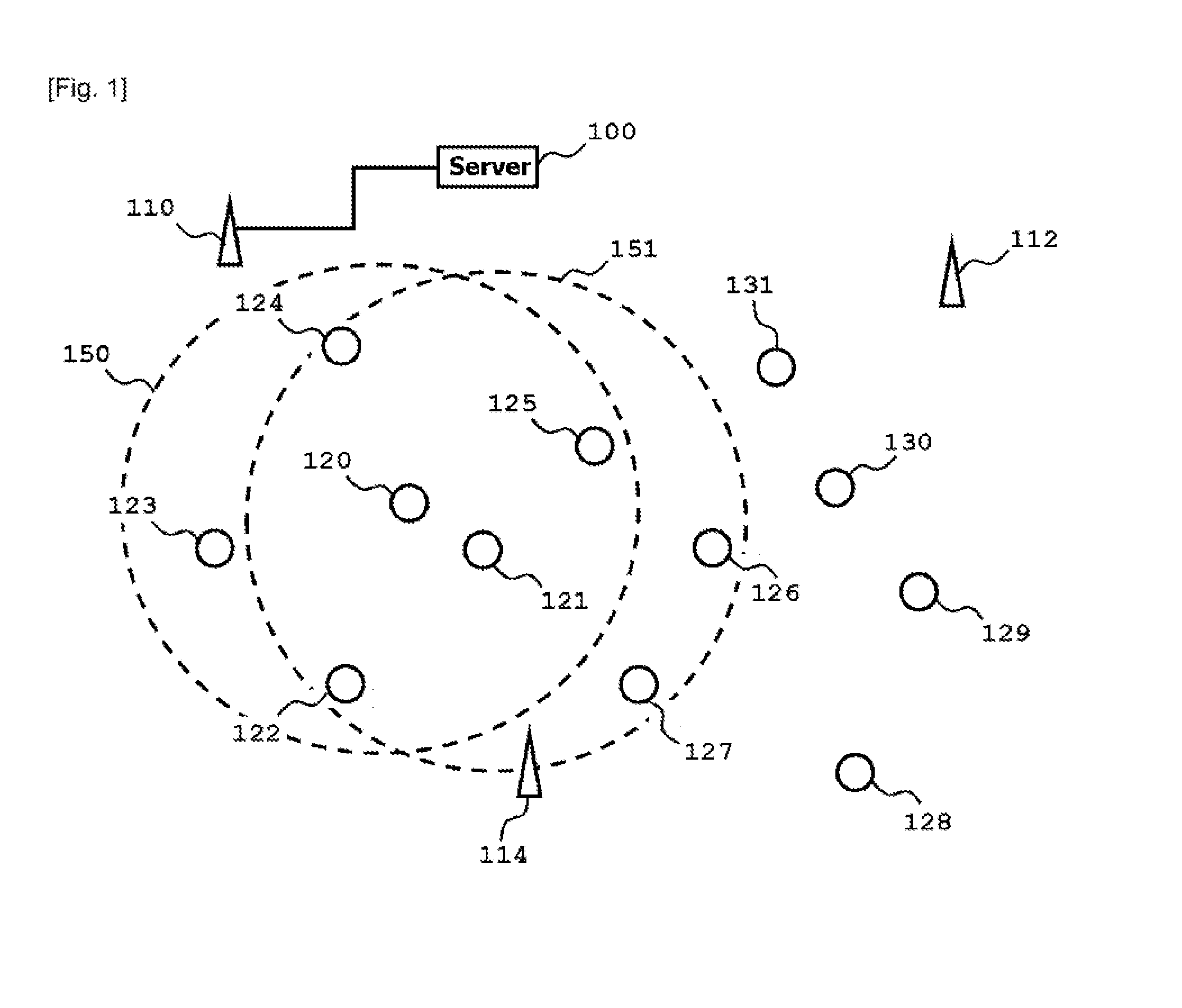
The patent text explains that in typical deployments, mobile nodes are closer to the target mobile node than the access points, which means that there is no need to deploy more access points or fixed anchors for position determination. This is a technical advantage of the invention.

Problems solved by technology

However, in urban areas, the presence of high-rise buildings blocking line-of-sights to GPS satellites has resulted in difficulties of locating one's position using GPS.
While the afore-mentioned methods are shown to be successful in outdoor environment, there has been increasing interest to perform location determination in indoor situation where these methods are either impractical or have poor performances.
These methods require there to be nodes with location determination capabilities that are independent from the wireless communications, which may not always be possible in some deployment scenarios.
Only methods that use only RSSI can have wide applicability, as specialized or expensive hardware are required to perform the measurements of the other wireless transmission parameters, which cannot be taken using readily available wireless chipset on the market.
The main problem with the fingerprinting method is that prior RSSI needs to be observed and recorded at every point in the area of location determination, making it not feasible in some deployments.

Method used


Image

  • Method for determination of wireless terminals positions and associated system and apparatus thereof
  • Method for determination of wireless terminals positions and associated system and apparatus thereof
  • Method for determination of wireless terminals positions and associated system and apparatus thereof

Examples


Embodiment Construction

[0054]In the following description, for purposes of explanation, specific numbers, times, structures, protocol names, and other parameters are set forth in order to provide a thorough understanding of the present invention. However, it will be apparent to anyone skilled in the art that the present invention may be practiced without these specific details.

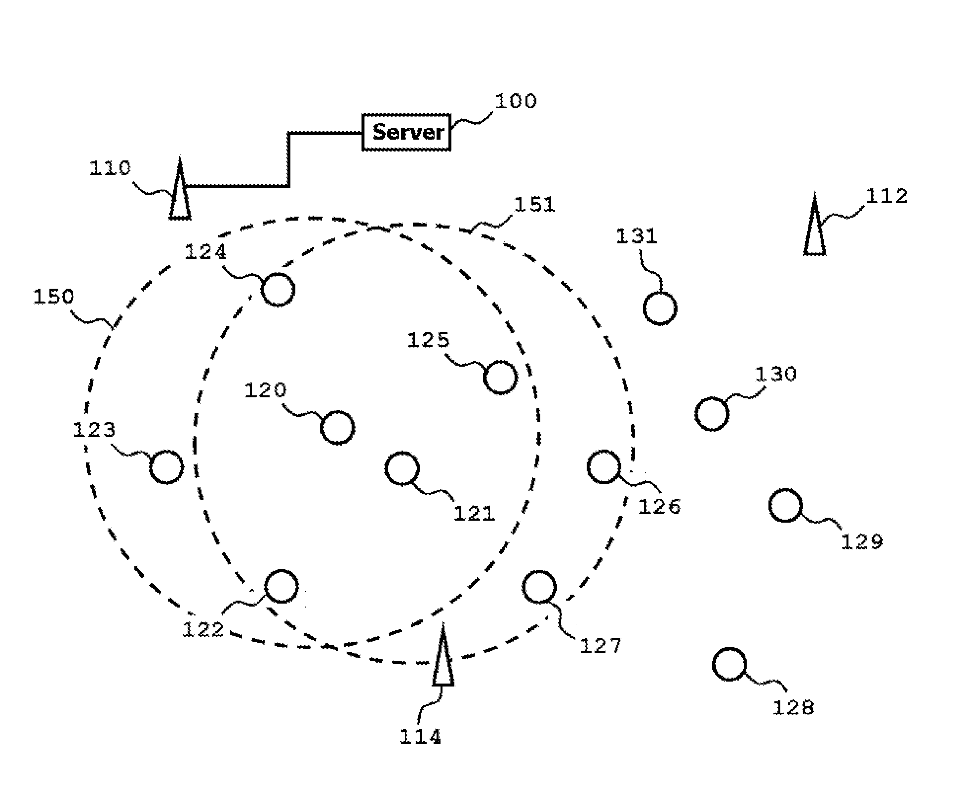
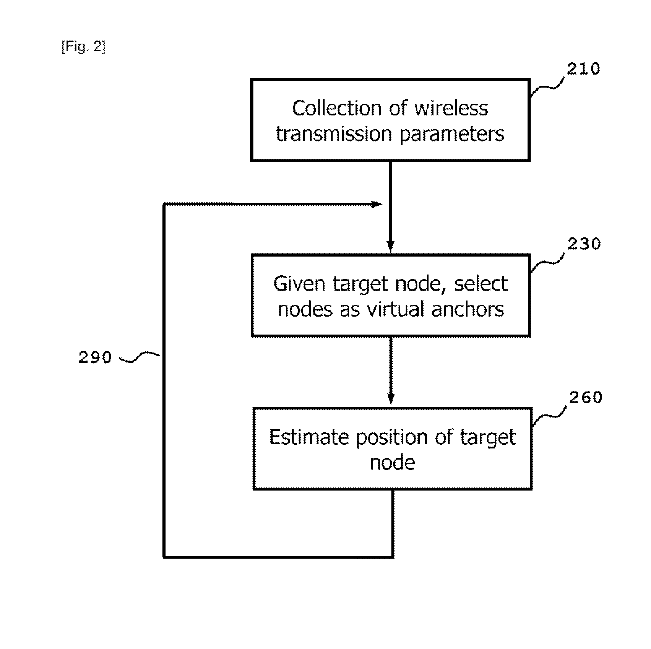
[0055]The present invention overcomes the problems associated with the prior art by selecting one or more mobile nodes as “virtual anchors” when estimating the position of a target mobile node. This takes advantage of the fact that mobile nodes are closer to the target mobile node than the access points in most typical deployments, thus eliminating the need to deploy more access points or fixed anchors for the purpose of position determination. After obtaining an initial estimation of the position of the target mobile node, the target mobile node can serve as virtual anchors to estimate the positions of other mobile nodes, which can...


PUM


Abstract

Conventional position estimation methods require the deployment of more fixed anchors in order to increase the accuracy in a crowded indoor environment, or they suffer from inaccuracies due to multipath fading. The present invention overcomes the problems associated with the prior arts by selecting one or more mobile nodes as virtual anchors when estimating the position of a target mobile node. This takes advantage of the fact that mobile nodes are closer to the target mobile node than the access points in most typical deployments, thus eliminating the need to deploy more access points or fixed anchors for the purpose of position determination. After obtaining an initial estimate of the position of the target mobile node, the target mobile node can serve as virtual anchors to estimate the positions of other mobile nodes, which can then be used to further refine the position estimate of the target mobile node.

Description

TECHNICAL FIELD[0001]This invention relates to the field of wireless communications. More particularly, it concerns the determination of the position of a single or plurality of wireless communication devices using the signals transmitted and received during wireless communications.BACKGROUND ART[0002]With the proliferation of wireless communications technology, more and more devices are equipped with wireless communications capabilities, such as Bluetooth, IEEE 802.11, or Zigbee. With wireless communications capabilities, the devices are no longer tethered to a fixed location, and can freely move about together with the users. This gives rise to an important application for wireless devices: to be able to provide location and navigation related services. The ubiquity of Global Positioning System (GPS) has allowed users to tell their current locations through the use of GPS-equipped devices. However, in urban areas, the presence of high-rise buildings blocking line-of-sights to GPS ...

Claims


Application Information

Patent Timeline
IPC IPC(8): G01S5/06G01S5/02
CPCG01S5/06H04W64/00H04W84/12H04W84/18
Inventor NG, CHAN WAHCHENG, KIAN SOONTAN, PEK YEW
Owner SUN PATENT TRUST
Learn More