Intervertebral support
- Summary
- Abstract
- Description
- Claims
- Application Information
AI Technical Summary
Benefits of technology
Problems solved by technology
Method used
Image
Examples
Embodiment Construction
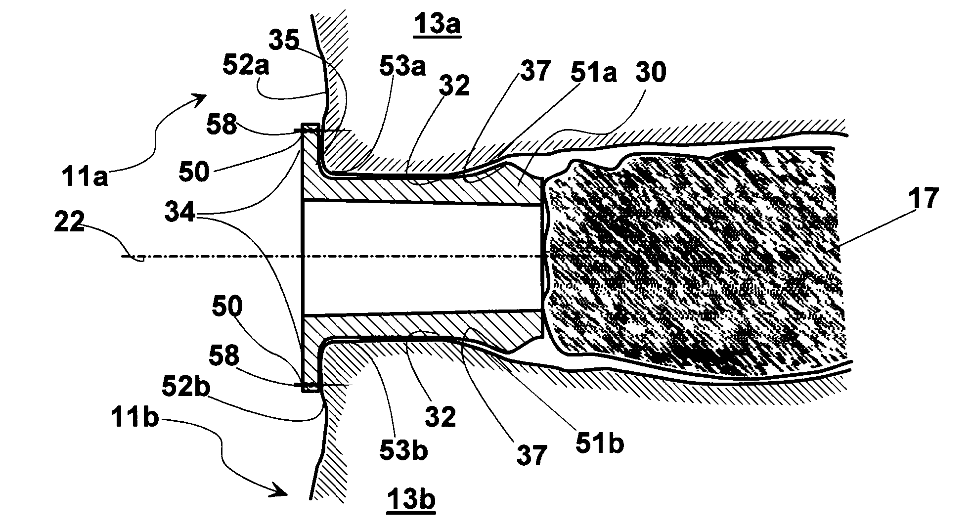
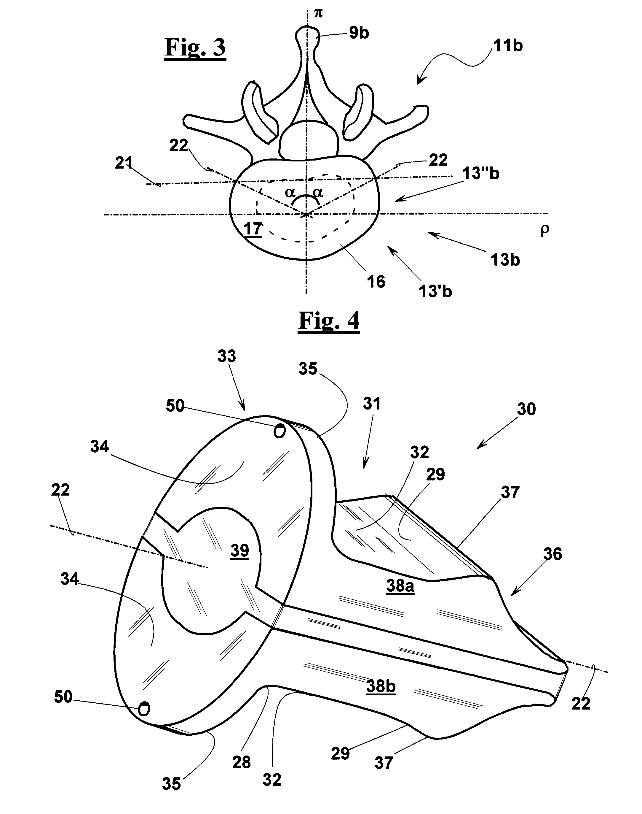
[0125]With reference to FIGS. 4 and 5, a support element 30, 30′ of an intervertebral support device is described according to two examples of a first exemplary embodiment of the invention. Support element 30, 30′ has an elongated shape and extends along an axis 22. Support element 30, 30′ is configured to be inserted between edge portions 53a, 53b of rear halves 13″a, 13″b of adjacent vertebral bodies 13a, 13b of a patient's spine 11, as diagrammatically shown in FIGS. 6 and 7.
[0126]Support element 30, 30′ has a central elongated portion 31 that provides support surfaces 32 for adjacent vertebral bodies 13a, 13b.
[0127]In the shown example, support element 30, 30′ comprises a medial end portion 36. Medial end portion 36 comprises protruding parts 37 which protrude with respect to support surface 32. In use, protruding parts 37 abut against respective inner surfaces 51a, 51b of adjacent vertebral bodies 13a, 13b. As FIG. 7 shows more in detail, protruding parts 37 oppose the expulsi...
PUM
 Abstract
Description
Claims
Application Information
 - R&D
- Intellectual Property
- Life Sciences
- Materials
- Tech Scout
- Unparalleled Data Quality
- Higher Quality Content
- 60% Fewer Hallucinations
Browse by: Latest US Patents, China's latest patents, Technical Efficacy Thesaurus, Application Domain, Technology Topic, Popular Technical Reports.
© 2025 PatSnap. All rights reserved.Legal|Privacy policy|Modern Slavery Act Transparency Statement|Sitemap|About US| Contact US: help@patsnap.com


