
Deposition apparatus

Inactive Publication Date: 2013-10-24
SAMSUNG SDI CO LTD
View PDF11 Cites 14 Cited by
  • Summary
  • Abstract
  • Description
  • Claims
  • Application Information

AI Technical Summary

Benefits of technology

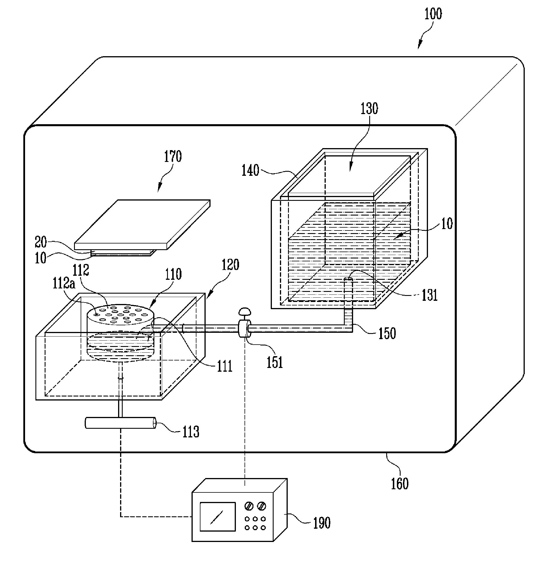
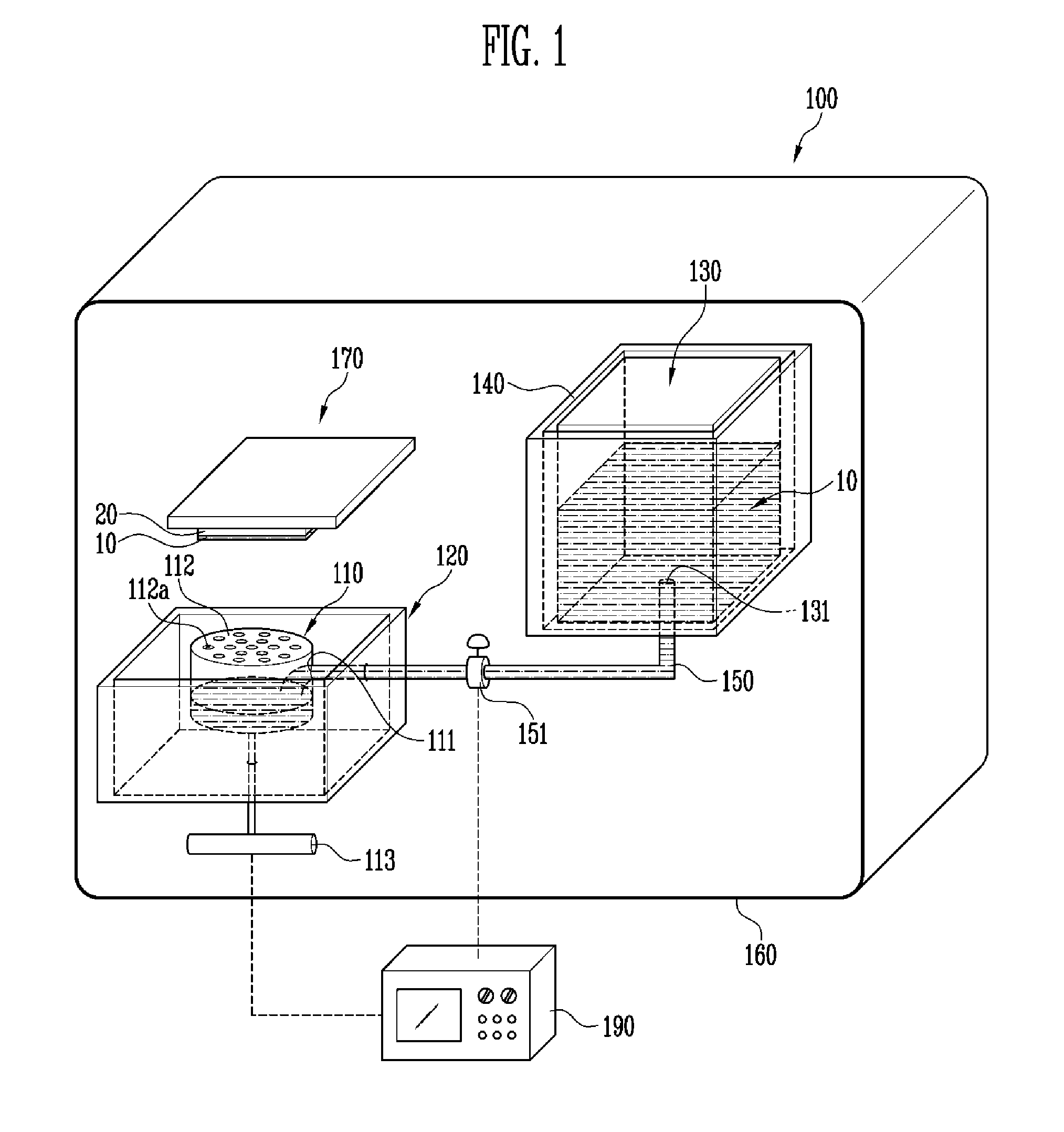
The present invention provides a deposition apparatus that can continuously perform a deposition process. Additionally, the apparatus is small in size and has a unique structure.

Problems solved by technology

In this case, since the source in the container is reduced as the deposition process is performed, the reduction of the source may result in unequal deposition.
Accordingly, it is difficult to control the property of the thin film.
On the other hand, a general deposition apparatus has no component capable of constantly maintaining the amount of source.
Therefore, it is difficult to obtain a uniform thickness of the thin film, and a problem of operator's safety may occur.

Method used


Image

  • Deposition apparatus
  • Deposition apparatus
  • Deposition apparatus

Examples


Embodiment Construction

[0044]In the following detailed description, only certain exemplary embodiments of the present invention have been shown and described, simply by way of illustration. As those skilled in the art would realize, the described embodiments may be modified in various different ways, all without departing from the spirit or scope of the present invention. Accordingly, the drawings and description are to be regarded as illustrative in nature and not restrictive.

[0045]In addition, when an element is referred to as being “on” another element, it can be directly on the another element or be indirectly on the another element with one or more intervening elements interposed therebetween. Also, when an element is referred to as being “connected to” another element, it can be directly connected to the another element or be indirectly connected to the another element with one or more intervening elements interposed therebetween. Hereinafter, like reference numerals refer to like elements.

[0046]Her...


PUM

PropertyMeasurementUnit
Temperatureaaaaaaaaaa
Fractionaaaaaaaaaa
Fractionaaaaaaaaaa

Abstract

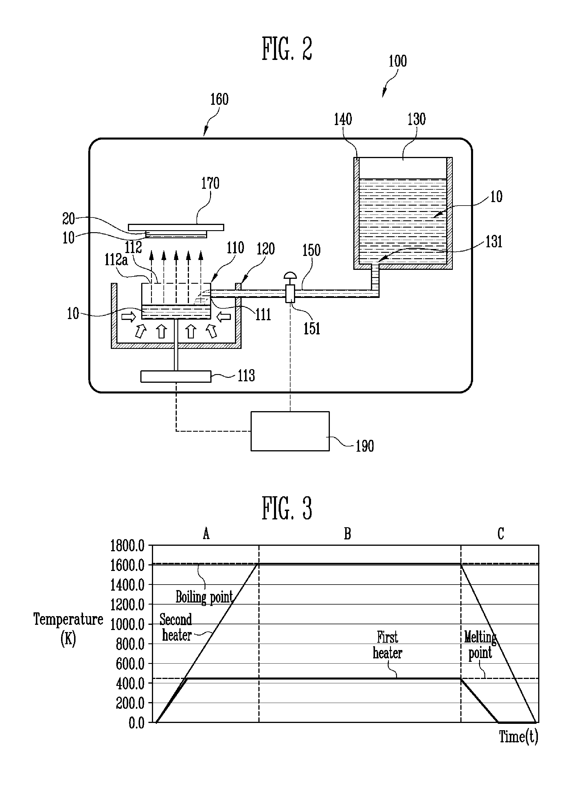
A deposition apparatus includes a crucible having an inlet, a first heater heating the crucible, a tank supplying an object to be deposited to the crucible and having an outlet, a second heater heating the tank, and a transfer pipe connecting the outlet of the tank and the inlet of the crucible. The first heater has a first temperature range, and the second heater has a second temperature range lower than the first temperature range. The object to be deposited may be liquefied within the tank and transferred in the liquid state to the crucible via the transfer pipe. The amount of the object to be deposited within the crucible may be continuously maintained at an approximately constant value by regulation of the flow of the liquefied object to be deposited from the tank to the crucible based upon the weight of the object to be deposited within the crucible.

Description

CROSS-REFERENCE TO RELATED APPLICATIONS[0001]This application claims priority to and the benefit of Korean Patent Application No. 10-2012-0042012, filed on Apr. 23, 2012, in the Korean Intellectual Property Office, the entire content of which is incorporated herein by reference.BACKGROUND[0002]1. Field[0003]Embodiments of the present disclosure relate to a deposition apparatus, and more particularly, to a deposition apparatus capable of continuously performing a deposition process for a long period of time.[0004]2. Description of the Related Art[0005]Apparatuses used for deposition are divided into an apparatus using heat and an apparatus using an electron beam. The apparatus using the heat uses a method of performing deposition by heating a source (e.g., the object to be deposited) using the heat. The apparatus using the electron beam uses a method of performing deposition by evaporating a source while converting electric energy transferred by an accelerated electron beam into ther...

Claims


Application Information

Patent Timeline
IPC IPC(8): C23C16/448
CPCC23C16/4485C23C14/14C23C14/24C23C14/246
Inventor LEE, SEUNG-HWANLEE, SUNG-HO
Owner SAMSUNG SDI CO LTD
Learn More