
Inhalation Devices and Systems and Methods Including the Same

a technology of inhalation device and airbag, which is applied in the direction of inhalators, respirators, etc., can solve the problems of ineffective or efficient patients generally having not made optimum use of and/or obtained optimal benefits from medications, and a large proportion of patients having not been able to achieve the effect of direct use of aerosol canisters

Active Publication Date: 2013-10-24
CERECOR INC
View PDF22 Cites 41 Cited by
  • Summary
  • Abstract
  • Description
  • Claims
  • Application Information

AI Technical Summary

Benefits of technology

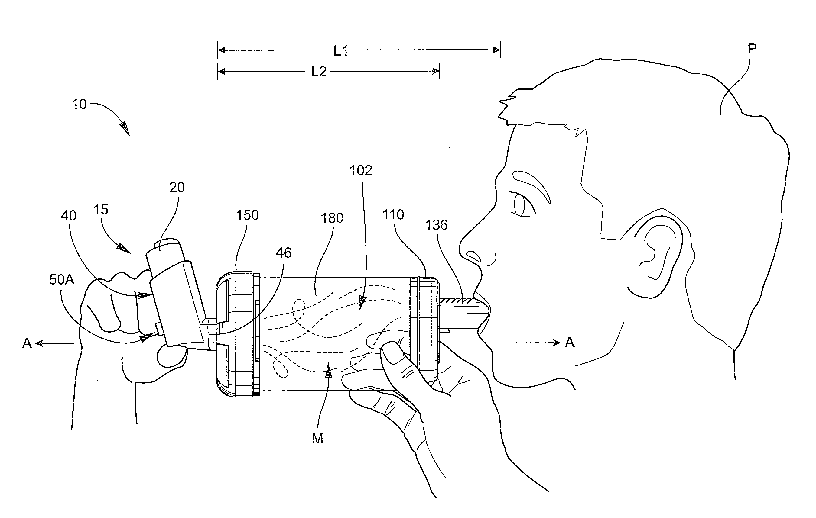
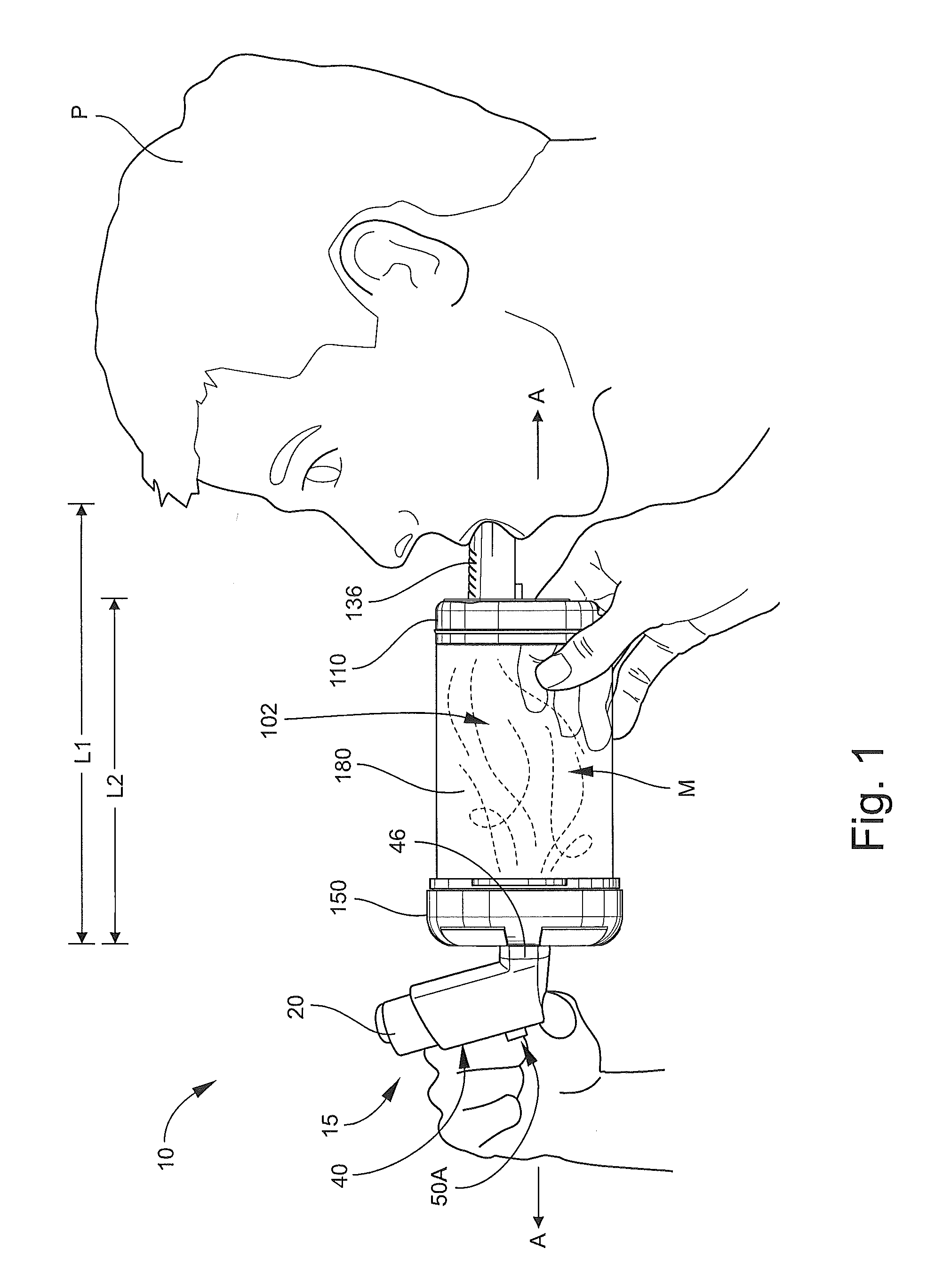
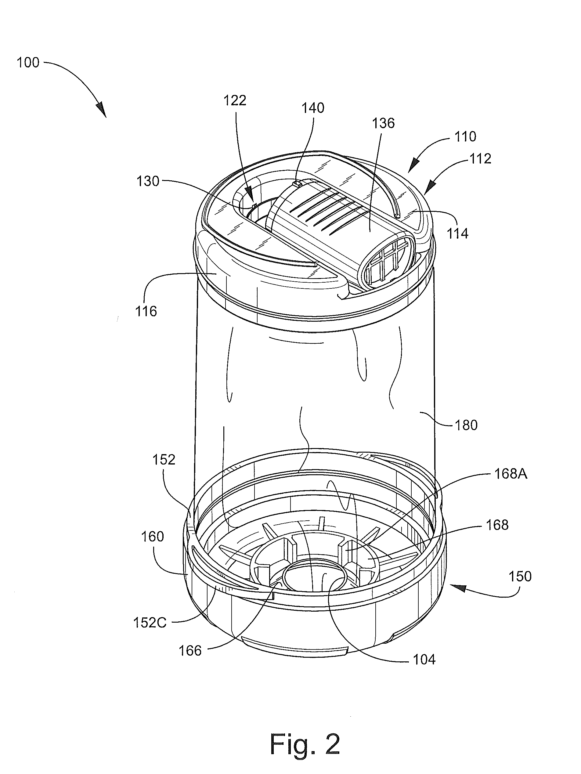
The patent describes a collapsible inhalation device that can be used with a metered dose inhaler. The device has a mouthpiece and a chamber for inhaling the medication. It includes a one-way inhalation valve and a one-way blowback relief valve to prevent air from flowing in the wrong direction. The device also has a trap structure to catch any components of the valves and prevent them from being inhaled. The device can be easily collapsed for easy storage and is designed to provide a safe and effective delivery of medication for patients.

Problems solved by technology

While medications can be dispensed directly from such canisters into the oronasal passages of patients, experience has proven that patients generally have not made optimum use of and / or have not obtained optimum benefits from medications delivered directly from the aerosol canisters.
Because direct use of the aerosol canisters has not proven effective or efficient for a large proportion of patients, many devices have been proposed for converting the medications from the concentrated pressurized form in which they are discharged from aerosol canisters into a nonpressurized and less concentrated form in order to be more readily and efficaciously inhaled by the patient.

Method used


Image

  • Inhalation Devices and Systems and Methods Including the Same
  • Inhalation Devices and Systems and Methods Including the Same
  • Inhalation Devices and Systems and Methods Including the Same

Examples


Embodiment Construction

[0051]The present invention now will be described more fully hereinafter with reference to the accompanying drawings, in which illustrative embodiments of the invention are shown. In the drawings, the relative sizes of regions or features may be exaggerated for clarity. This invention may, however, be embodied in many different forms and should not be construed as limited to the embodiments set forth herein; rather, these embodiments are provided so that this disclosure will be thorough and complete, and will fully convey the scope of the invention to those skilled in the art.

[0052]It will be understood that when an element is referred to as being “coupled” or “connected” to another element, it can be directly coupled or connected to the other element or intervening elements may also be present. In contrast, when an element is referred to as being “directly coupled” or “directly connected” to another element, there are no intervening elements present. Like numbers refer to like elem...


PUM


Abstract

A collapsible inhalation device for use with a metered dose inhaler (MDI) dispenser includes an outlet end member, an inlet end member and a tubular, pliable, collapsible sleeve member attached at either end to the inlet and outlet members. The outlet end member includes a mouthpiece. The inlet end member includes an inlet port and an MDI dispenser mount structure configured to receive and engage the MDI dispenser. The inhalation device is positionable in each of an open position, wherein the sleeve member defines a chamber, and a closed position, wherein the sleeve member is collapsed and enveloped by the outlet end member and the inlet end member. When the inhalation device is in the open position with the MDI dispenser mounted in the MDI dispenser mount structure, a dose of the medication can be dispensed from the MDI dispenser into the chamber through the inlet port to mix with air in the chamber and thereby form a mixture of the air and the dose of the medication that can be inhaled by a patient from the chamber through the mouthpiece.

Description

RELATED APPLICATION(S)[0001]This application claims the benefit of and priority from U.S. Provisional Patent Application No. 61 / 771,406, filed Mar. 1, 2013, and U.S. Provisional Patent Application No. 61 / 636,320, filed Apr. 20, 2012, the disclosures of which are incorporated herein by reference.FIELD OF THE INVENTION[0002]The present invention relates to inhalation devices and, more particularly, to inhalation devices and systems and methods including the same for delivering a dispersed dose of a medication for inhalation by a patient.BACKGROUND OF THE INVENTION[0003]Oronasal delivery of drugs has long been known and has gained wide acceptance. Pharmaceuticals for the treatment of tracheal, bronchial, nasal and pulmonary conditions are widely available in prescribed or metered doses in small pressurized aerosol canisters. While medications can be dispensed directly from such canisters into the oronasal passages of patients, experience has proven that patients generally have not made...

Claims


Application Information

Patent Timeline
Patent Type & Authority Applications(United States)
IPC IPC(8): A61M15/00A61M16/20
CPCA61M15/0086A61M16/208A61M15/009A61M15/0013A61M15/0016A61M15/0018A61M15/0021A61M15/0023A61M15/0068A61M15/0071A61M15/008A61M15/0081A61M15/0088A61M16/107A61M16/20A61M16/209
Inventor STEELMAN, PETER WAYNEFLYNN, JAMES EDWARDZEIS, JOHNWORLEY-HAM, KARLA
Owner CERECOR INC
Learn More