

Liquid droplet discharge device and method of manufacturing liquid droplet discharge device
- Summary
- Abstract
- Description
- Claims
- Application Information
AI Technical Summary
Benefits of technology
Problems solved by technology
Method used
Image

Examples
embodiment 1
Overall Configuration of Liquid Droplet Discharge Device
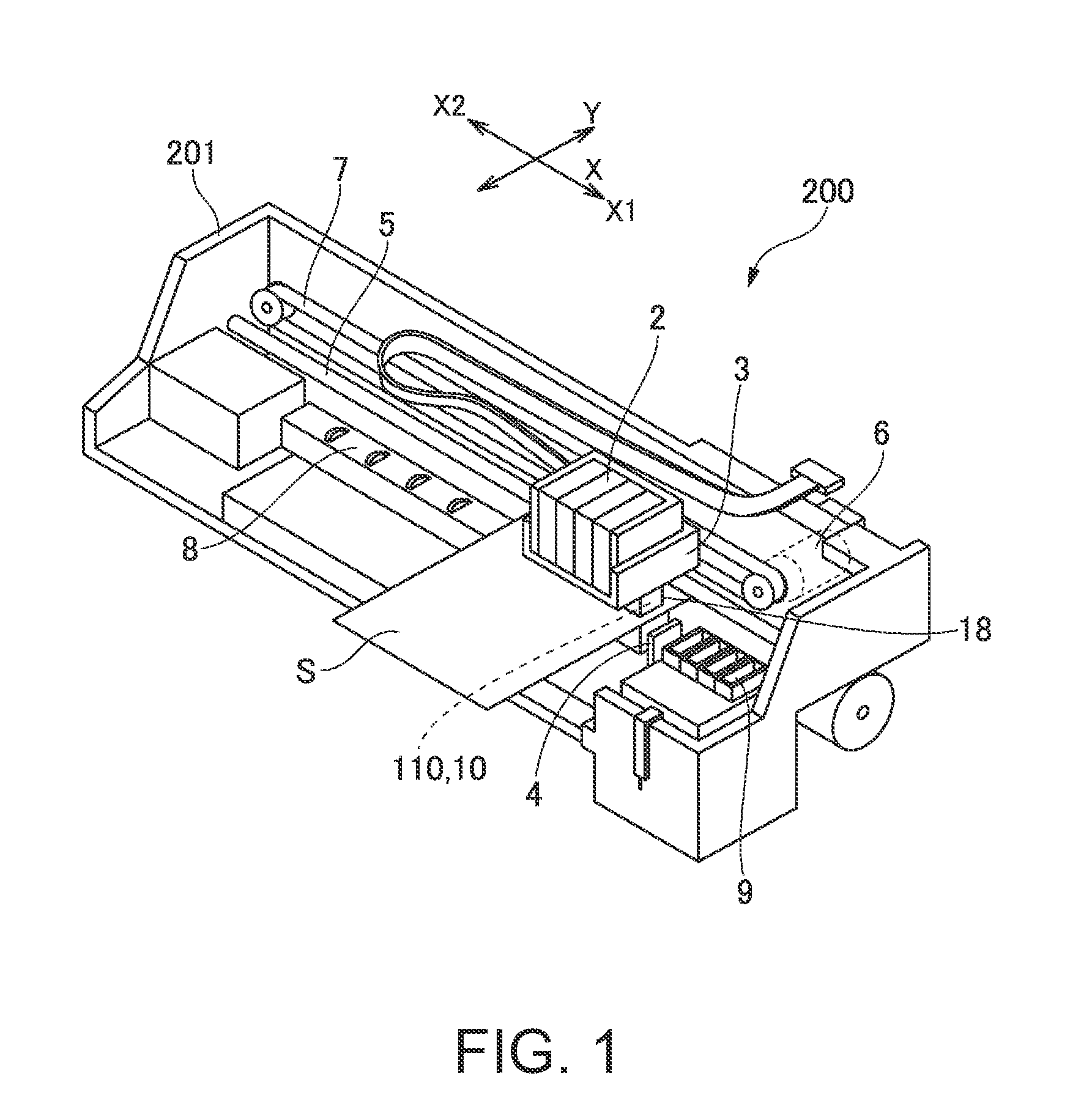
[0036]FIG. 1 an explanatory view of the liquid droplet discharge device related to Embodiment 1 of the invention. In FIG. 1, a liquid droplet discharge device 200 of the present embodiment is an ink jet printer that discharges liquid ink to a surface of a recoding medium S such as recording paper to record images or the like. The liquid droplet discharge device 200 includes a head assembly 110 including a plurality of liquid droplet discharge heads 10, a carriage 3 to which the head assembly 110 is attached, a carriage shaft 5 that supports the carriage 3 so as to be movable in the main scanning direction X, a platen 8 that transports the recording medium S in the auxiliary scanning direction Y or the like. The ink is stored in an ink cartridge 2, and the ink cartridge 2 and the head assembly 110 are mounted on the carriage 3. In addition, it is also possible to adopt a configuration in which the ink cartridge 2 is placed on a ...
embodiment 2
[0068]FIGS. 9A and 9B are explanatory views of the nozzle plate 1 of the liquid droplet discharge head 10 of the liquid droplet discharge device 200 related to Embodiment 2 of the invention, enlarged cross-sectional views showing an aspect in which the nozzle plate 1 of the liquid droplet discharge head 10 and the periphery thereof are cut in the main scanning direction X, and explanatory views showing an aspect in which the substrate 100 is formed with the grooves 12. In addition, since basic configurations of the present embodiment are the same as those of Embodiment 1, the common portions are denoted by the same reference numerals, and the descriptions thereof will be omitted. Furthermore, in FIGS. 9A and 9B, the liquid droplet discharge surface 1a of both surfaces of the nozzle plate 1 is shown upward.
[0069]As shown in FIG. 9A, in the liquid droplet discharge head 10 of the liquid droplet discharge device 200 of the present embodiment, as in Embodiment 1, the nozzle plate 1 is a...
embodiment 3
[0075]FIGS. 10A and 10B are explanatory views of the nozzle plate 1 of the liquid droplet discharge head 10 of the liquid droplet discharge device 200 related to Embodiment 3 of the invention, enlarged cross-sectional views showing an aspect in which the nozzle plate 1 of the liquid droplet discharge head 10 and the periphery thereof are cut in the main scanning direction X, and explanatory views showing an aspect in which the substrate 100 is formed with the grooves 12. In addition, since basic configurations of the present embodiment are those of the same as Embodiment 1, the common portions are denoted by the same reference numerals, and the descriptions thereof will be omitted. Furthermore, in FIGS. 10A and 10B, the liquid droplet discharge surface 1a of both surfaces of the nozzle plate 1 is shown upward.
[0076]As shown in FIG. 10A, in the liquid droplet discharge head 10 of the liquid droplet discharge device 200 of the present embodiment, as in Embodiment 1, the nozzle plate 1...
PUM
 Abstract
Description
Claims
Application Information