
Image capturing device and image capturing method

Active Publication Date: 2013-10-24
RICOH KK
View PDF3 Cites 12 Cited by
  • Summary
  • Abstract
  • Description
  • Claims
  • Application Information

AI Technical Summary

Benefits of technology

The object of the invention is to solve some of the problems in the current technology.

Problems solved by technology

It is already known that this AF range-finding scanning is time consuming because the AF range-finding scanning is performed by obtaining AF evaluation values while a focusing lens is moved over an entire area where the focusing lens is movable and selecting peak positions one after another.
H04-158322 or No. 2010-128395 that allows designating an object to be focused is also time consuming in processing time involved in auto focusing, which can result in losing a good opportunity for shooting a photograph.

Method used


Image

  • Image capturing device and image capturing method
  • Image capturing device and image capturing method
  • Image capturing device and image capturing method

Examples


first embodiment

[0085]First, the first embodiment of the high-speed continuous shooting process to be performed by the digital still camera according to the present embodiment is described. FIG. 12 is a flowchart illustrating a processing flow from the viewfinder mode to high-speed continuous shooting of the first embodiment. Description will be made below with reference to the flowchart.

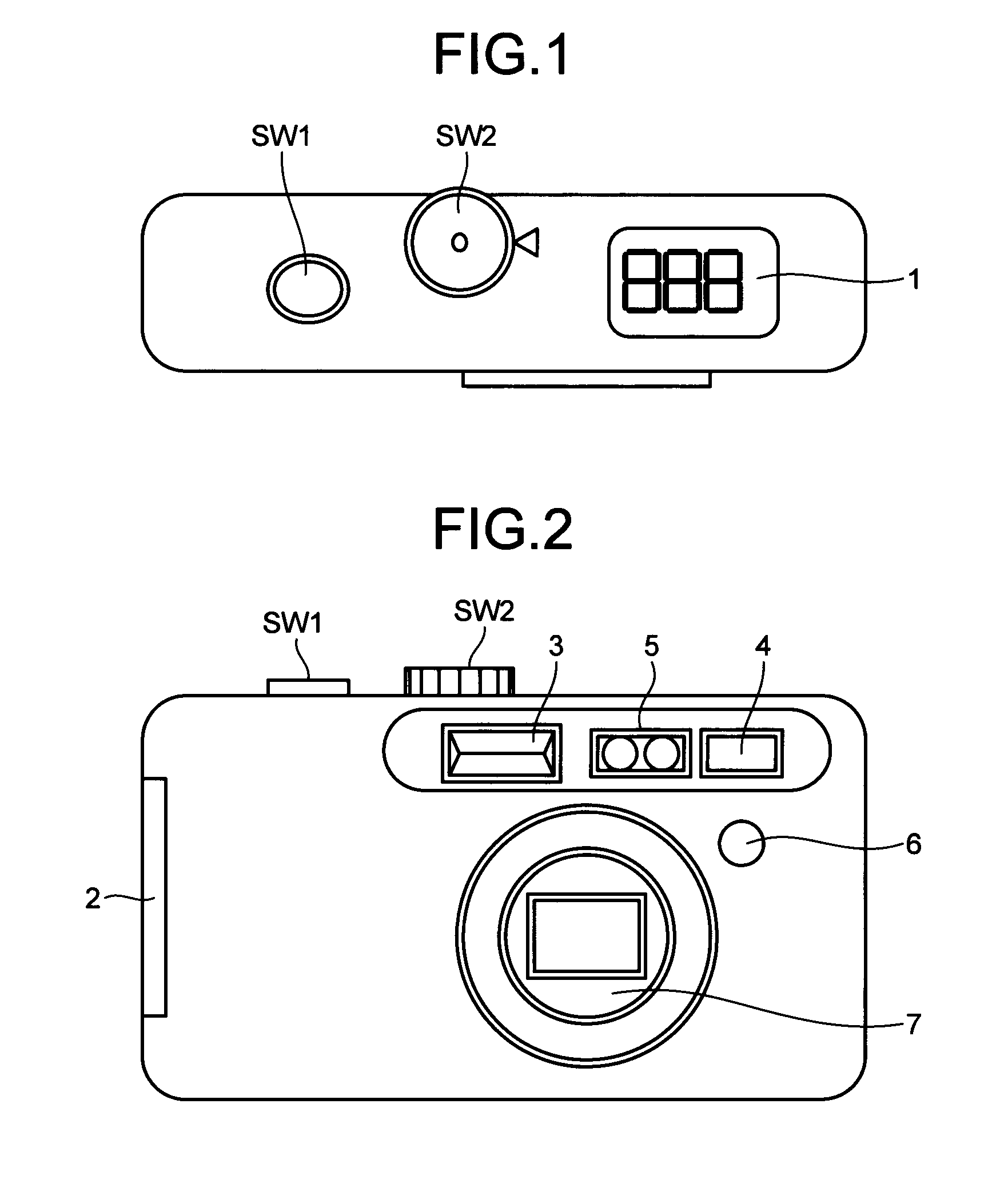
[0086]Immediately after power supply is turned on, the digital still camera is in the viewfinder mode. In the viewfinder mode, a range-finding process by using the range-finding unit 5 is performed first (S12-1). The range-finding process is described with reference to flowcharts of FIGS. 15 and 16.

[0087]First, the CPU block 204-2 performs a photometry process (S15-1) according to the control program (range-finding processing unit) stored in the ROM 206 inside the range-finding unit 5. The photometry process (S15-1) is illustrated in the flowchart of FIG. 16.

[0088]First, evaluation values for automatic exposure are...

second embodiment

[0108]A second embodiment of the high-speed continuous shooting process that can be performed by the digital still camera is described below. A basic processing flow from the viewfinder mode to the high-speed continuous shooting of the second embodiment is substantially the same as that described in the first embodiment with reference to the flowchart of FIG. 12. The range-finding process using the range-finding unit 5 is also substantially the same as that described in the first embodiment with reference to FIGS. 15, 16, and 17. Processes that characterize the second embodiment, in addition to the basic processing flow from the viewfinder mode to the high-speed continuous shooting, are described below.

[0109]First, when the power supply to the digital still camera is turned on, the digital still camera is set to be in the viewfinder mode. In the viewfinder mode, the range-finding process by using the range-finding unit 5 is performed first (S12-1). The range-finding process is subst...


PUM


Abstract

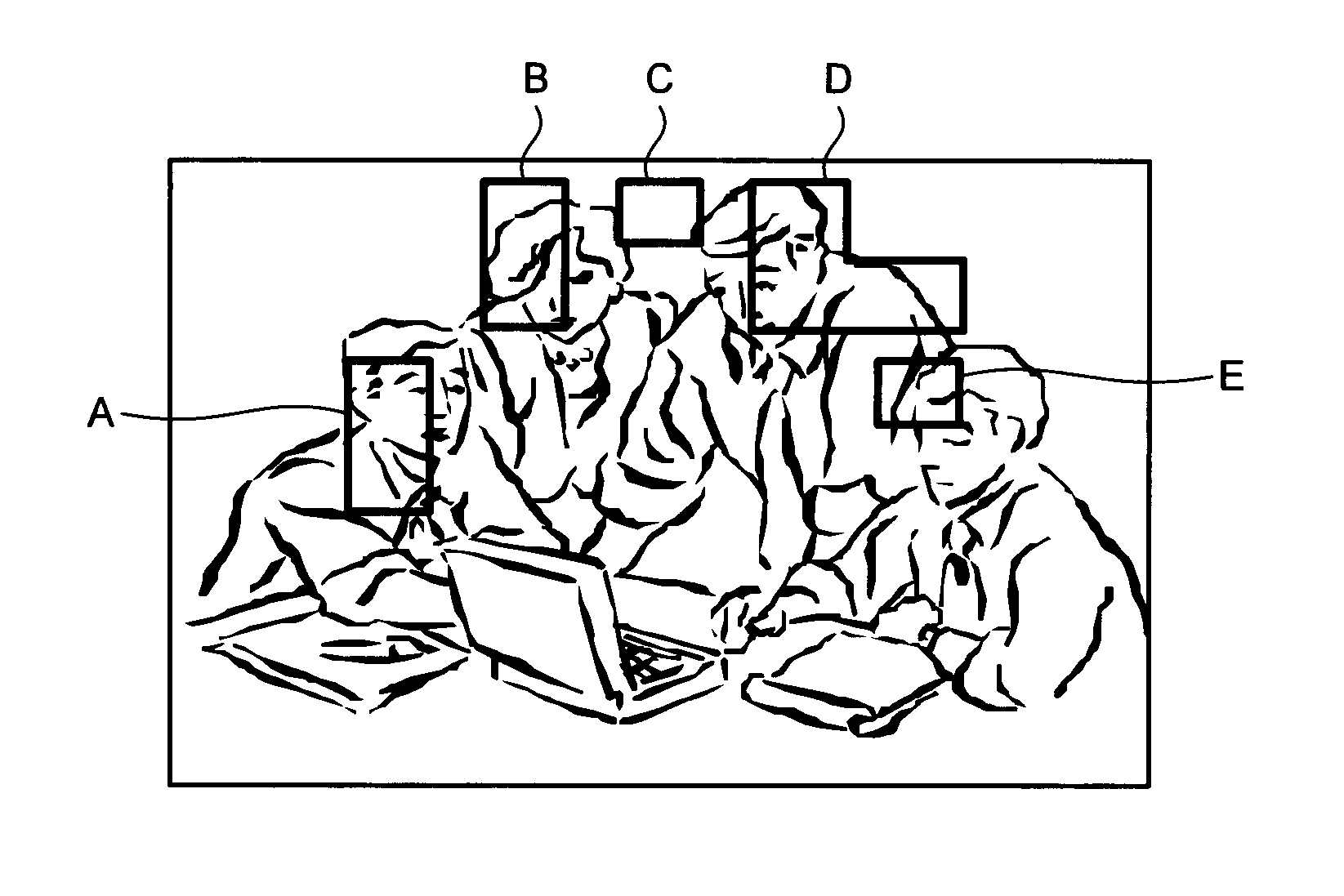
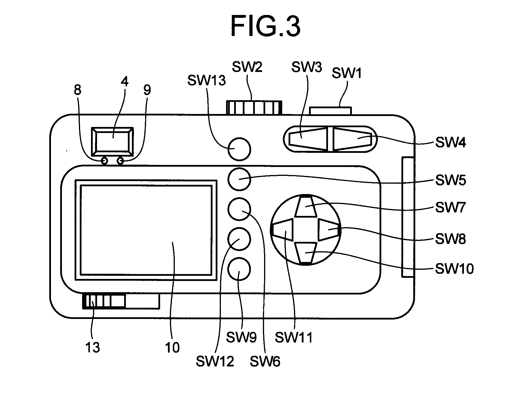
An image capturing device includes: an image capturing unit that captures a subject image through a lens and converts the subject image into an electric signal; an image displaying unit that displays an image; a designation accepting unit that is provided on a display surface of the image displaying unit and that accepts designation of a plurality of positions on the image displayed on the image displaying unit; a range-finding unit that performs range finding of a distance to a subject by using a plurality of two-dimensional image sensors; an area setting unit that sets a range-finding area obtained from a range finding result for a region that includes the plurality of positions designated through the designation accepting unit; a position determining unit that determines in-focus positions based on distances of the range-finding areas; and a continuous shooting unit that performs image capturing at the in-focus positions.

Description

TECHNICAL FIELD[0001]The present invention relates to an image capturing device and an image capturing method.BACKGROUND ART[0002]An electronic image capturing device, such as a digital still camera, generally includes an autofocus (AF) unit that automatically focuses on an object. As an AF control method for the AF unit, hill-climbing AF control is widely used (see, for example, Japanese Examined Patent Application Publication No. S39-5265). The hill-climbing AF control is performed by calculating an integral of differences in luminance of adjacent pixels based on a video signal output from an image sensor and by using the integral of the differences in luminance as an AF evaluation value for evaluating a degree of focusing. At an in-focus state, edge portion of an object is highly contrasting, and hence the differences in luminance of the neighboring pixels are large; accordingly, the AF evaluation value is large. In contrast, in an out-of-focus state, the edge portion of the obje...

Claims


Application Information

Patent Timeline
IPC IPC(8): H04N5/232G02B7/28G02B7/30G03B7/00G03B13/36G03B15/00G03B17/02H04N5/225H04N101/00
CPCH04N5/23293G02B7/38G03B13/20G03B13/36G03B17/18H04N23/675H04N23/61H04N23/611H04N23/62H04N23/635G02B7/28G02B7/30
Inventor ITOH, KEIITO, YOICHI
Owner RICOH KK
Learn More