Method and system for determining the location of a fiber optic channel along the length of a fiber optic cable

a technology of fiber optic cable and location method, which is applied in the field of method and system for determining the location of a fiber optic channel along the length of a fiber optic cable, can solve the problems of small changes in the fiber, insufficient calculation accuracy, and inability to produce backscattered light signals

Inactive Publication Date: 2013-10-24
SHELL OIL CO
View PDF2 Cites 25 Cited by
  • Summary
  • Abstract
  • Description
  • Claims
  • Application Information

AI Technical Summary

Benefits of technology

[0018]It will be understood that if a magnetic field source is arranged adjacent to an assembly of a fiber optic channel and adjacent electrical conductor this will generate a Lorentz force or other electromagnetic effect, such as a magneto-restrictive force, which enables to establish the location of the magnetic field source with respect to the fiber optic channel. The Lorentz force can be applied by including an electrical conductor deployed near the fiber optic cable and passing a current through the electrical conductor so as to cause it to deform as a result of the magnetic field generated by the magnetic field source. In these instances, an optical signal can be used in conjunction with OTDR in the fiber optic channel to detect the deformation and thereby determine location of the channel. The magnetic field source may or may not be fixed with respect to the fiber optic cable.

Problems solved by technology

Localized strain or other disruptions cause small changes to the fiber, which in turn produce changes in the backscattered light signal.
In some applications, including downhole applications, the physical channel depths cannot practically be measured directly, but they can be roughly inferred on the basis of timing and fiber refraction index, i.e. the “optical depth.” These rough calculations are not sufficiently precise for some purposes, however, because they incorporate uncertainties that, while small on a percent scale, build to a significant magnitude over the length of the fiber.
Currently, however, there is no practical way to accurately determine the actual physical location of a given backscattered signal in an elongate optical fiber arranged in an elongate well or other encapsulation.

Method used


Image

  • Method and system for determining the location of a fiber optic channel along the length of a fiber optic cable
  • Method and system for determining the location of a fiber optic channel along the length of a fiber optic cable

Examples


Embodiment Construction

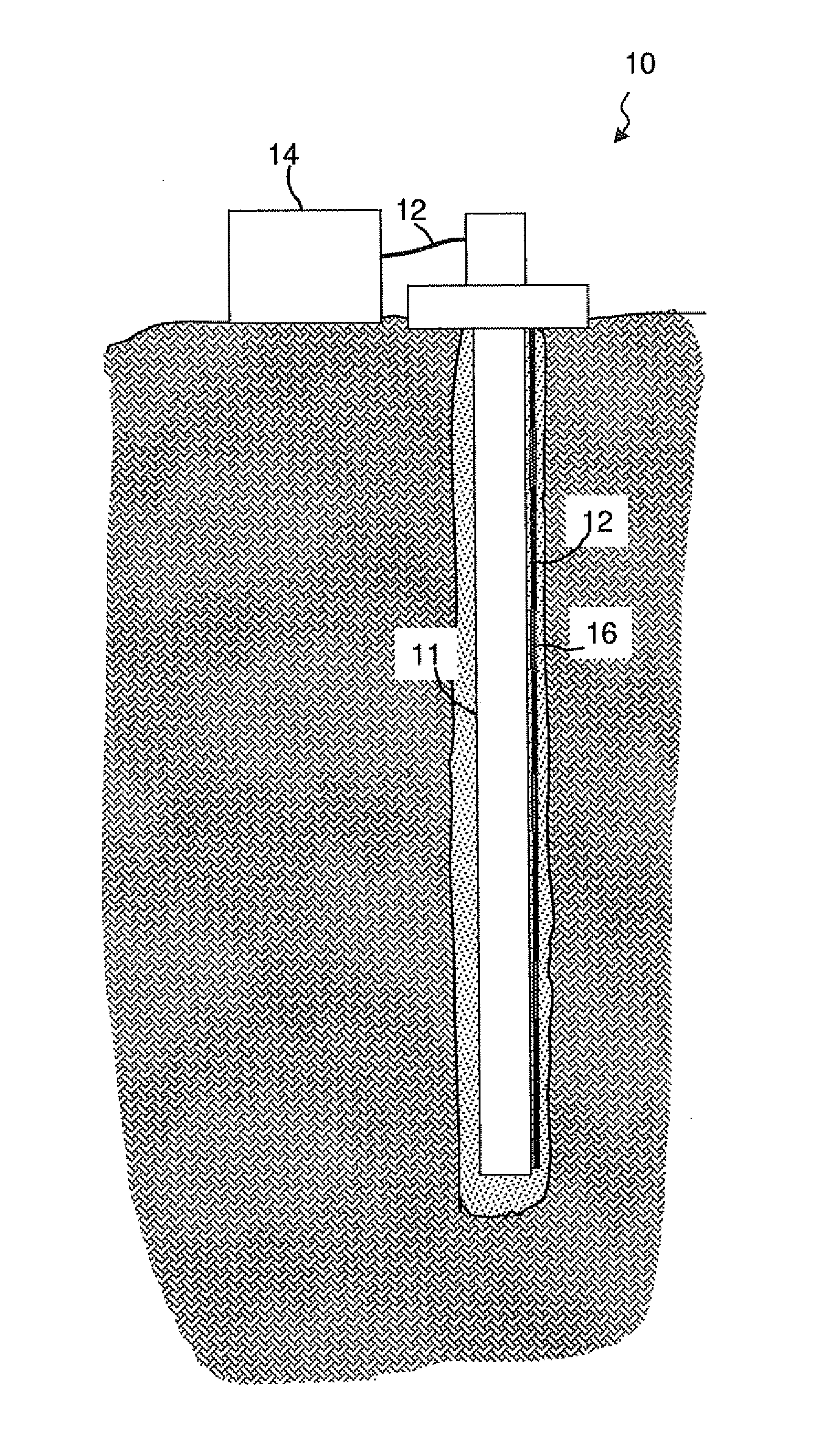
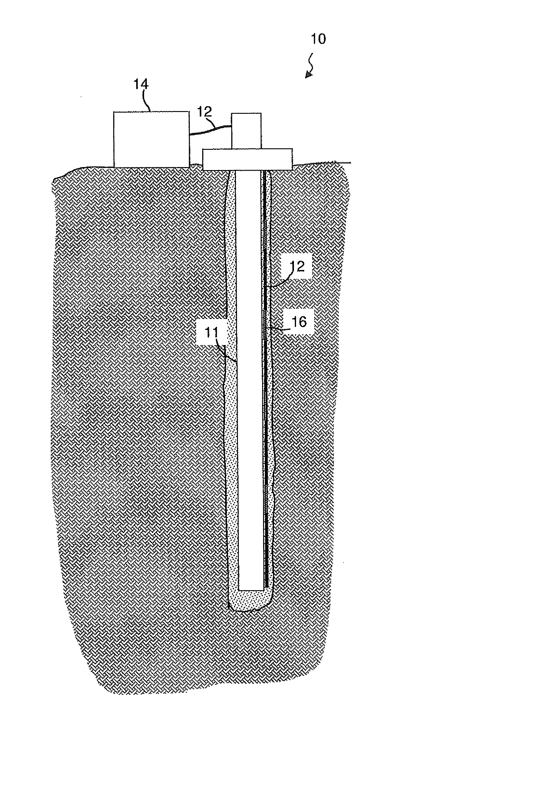
[0021]The present invention relates generally to a system and a method that allows the physical location of backscattered signals in a fiber optic cable to be determined with precision.

[0022]Referring initially to the FIGURE, a well 10 contains a fiber optic cable 12 that follows the well. Cable 12 is optically coupled at one end to a light box 14, such as are known in the art. Cable 12 may be double-ended, i.e. may be bent in the middle so that both ends of the cable are alternatively connected to the light source, or it may be single-ended, with one end at the source and the other end at a point that is remote from the light source. In the embodiment illustrated in the FIGURE, well 10 contains a tubular 11, such as a casing or liner. Cable 12 is run into the well in conjunction with tubular 11 and cement is pumped into the annulus between the tubular and the wellbore, thereby mechanically coupling cable 12 to the formation.

[0023]It will be understood by those skilled in the art th...


PUM


Abstract

The location of one or more fiber optic channels (16) along the length of a fiber optic cable (12) is determined by: a) arranging an electrical conductor and a magnetic source at a known location adjacent to at least one of the channels (16); b) transmitting an electrical current through the electrical conductor, thereby deforming the electrical conductor by Lorenz forces in the vicinity of the magnetic source; c) conveying the deformation of the electrical conductor to deform an adjacent channel (16); d) transmitting light pulses through the fiber optic cable (12) and using variations in the light pulses back reflected by the deformed channel (16) and the known location of the magnetic source to determine the location of the deformed channel (16).

Description

TECHNICAL FIELD OF THE INVENTION[0001]The present disclosure relates generally to a system and a method for improving the accuracy of location measurements made using fiber optic cable and backscattered light.BACKGROUND OF THE INVENTION[0002]The use of backscattered light in fiber optic cables has found increasing acceptance in a variety of applications. Because light can be backscattered from any location along the length of a fiber, information can be obtained over significant distances and such systems are often referred to as “distributed” sensors. Because distortion or deformation of the fiber can be sensed, distributed sensors comprised of fiber optic cable can be used to sense temperature, pressure, strain, acoustic events, and the like. Distributed systems have been used advantageously in oilfield applications, in traffic monitoring, and in military / security applications, among others.[0003]In a typical fiber optic-based distributed sensing system, one or more fiber optic ca...

Claims


Application Information

Patent Timeline
Patent Type & Authority Applications(United States)
IPC IPC(8): G02B6/00
CPCG02B6/00G01B7/02G01B11/02E21B47/092E21B47/12
Inventor JOINSON, DANIEL
Owner SHELL OIL CO
Why Eureka
Try Eureka