
Rivet fastener

Active Publication Date: 2013-10-24
ILLINOIS TOOL WORKS INC
View PDF6 Cites 6 Cited by
  • Summary
  • Abstract
  • Description
  • Claims
  • Application Information

AI Technical Summary

Benefits of technology

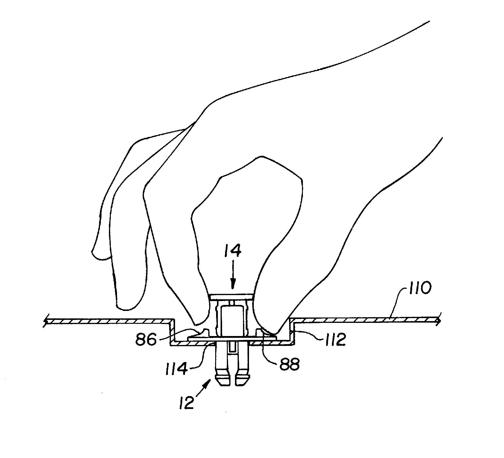
The present invention provides a rivet fastener with a narrow grip between the sides of the head of the pin, making it easier to handle and install, particularly in recessed cavities. The head of the body includes a channel for receiving the narrowed head of the pin, and the outer surface hollows laterally of the channel allowing the fingertips of an installer better access for inserting the pin into the body. This design improves the functionality of the rivet fastener.

Problems solved by technology

Advantages of at least some forms of the rivet fastener disclosed herein are that the rivet fastener is easier to handle and install, particularly in recessed cavities.

Method used


Image

  • Rivet fastener
  • Rivet fastener
  • Rivet fastener

Examples


Embodiment Construction

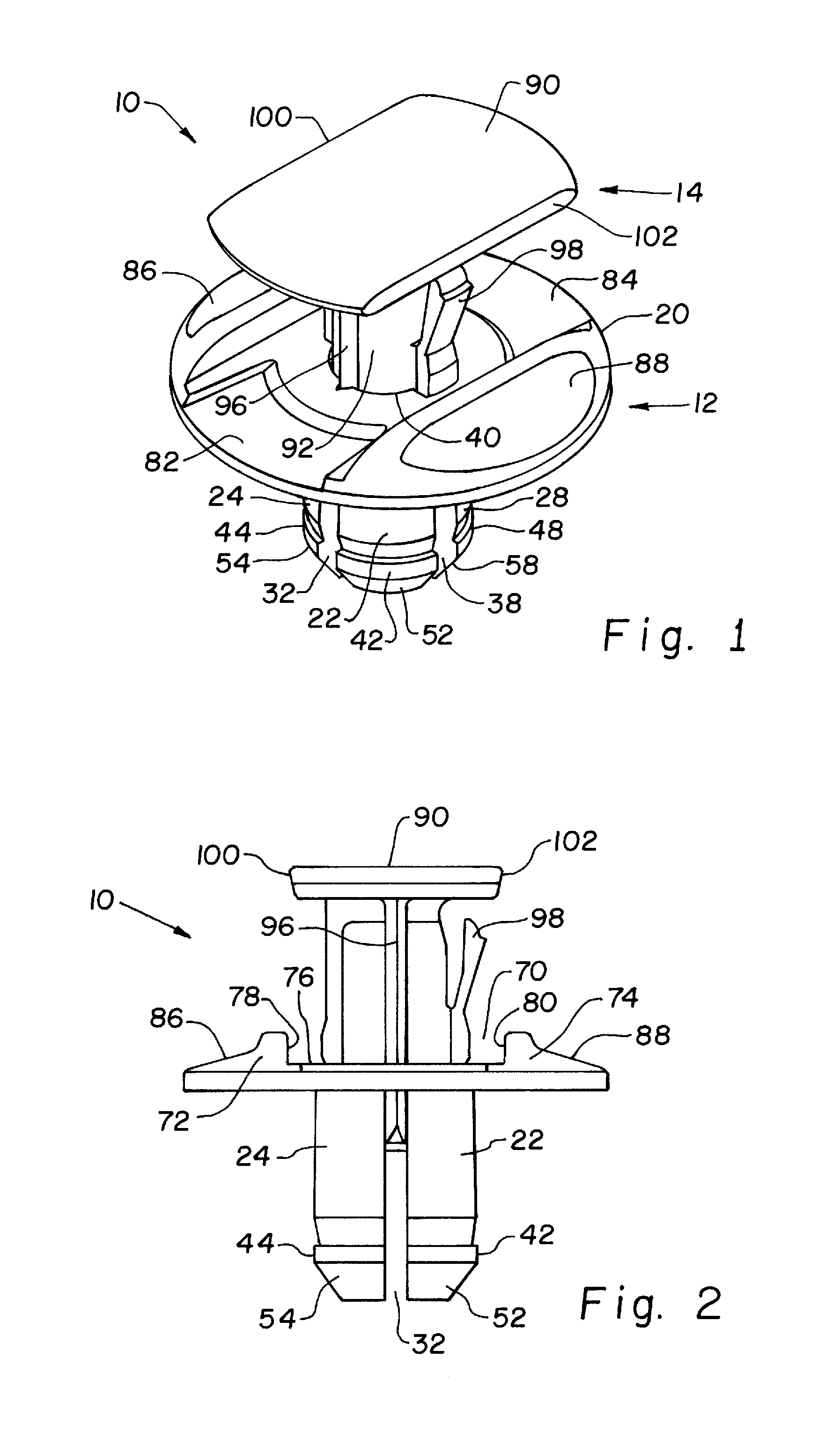
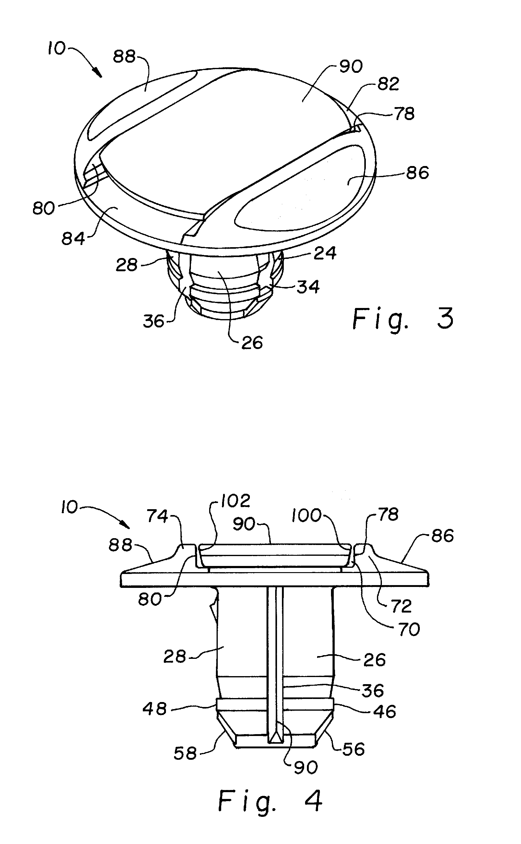
[0017]Referring now more specifically to the drawings and to FIG. 1 in particular, an exemplary rivet fastener 10 is shown. Fastener 10 includes a fastener body 12 and a fastener pin 14. Fastener body 12 is configured to seat within holes in articles to be fastened together by rivet fastener 10. Fastener pin 14 is configured for insertion into fastener body 12 to inhibit fastener body 12 from dislodging from the articles in which it is seated. Fastener body 12 and fastener pin 14 can be made of plastic by various molding techniques, and can be formed from the same or different materials.

[0018]Fastener body 12 includes a body head 20 and legs 22, 24, 26, 28 extending substantially axially from one side of body head 20. In the exemplary embodiment shown, legs 22, 24, 26, 28 are independent and spaced one from the other except for the mutual connection thereof to one side of body head 20. Accordingly, elongated spaces 32, 34, 36, 38 are defined between adjacent legs 22, 24, 26, 28, and...


PUM


Abstract

A rivet fastener includes a fastener body and a fastener pin which is inserted into the fastener body. A head of the fastener body defines a channel for receiving a head of the fastener pin, with lateral lands of the fastener body head exposed outwardly of sides of the fastener pin head. The exposed surface of the fastener body head defines hollows or recesses to accommodate tips of fingers of an installer.

Description

CROSS-REFERENCE TO RELATED APPLICATIONS[0001]The present application claims the benefits of U.S. Provisional Application Ser. No. 61 / 422,890 filed Dec. 14, 2010.FIELD OF THE INVENTION[0002]The present invention relates generally to fasteners, and more particularly to plastic, rivet-type fasteners used for securing articles to supporting structures, such as, for example, the fasteners used in the automotive industry to secure interior panels, interior and exterior molding and trim, and the like.BACKGROUND OF THE INVENTION[0003]A basic design for a rivet-type fastener includes a body that is inserted into aligned openings in first and second articles. The fastener body includes a collar or head larger than the openings in the articles, and deflectable portions that yield as the body is inserted through the openings and rebound when fully through the openings. The articles to be secured by the fastener are sandwiched between the collar and the rebounded deflectable portions. A pin of t...

Claims


Application Information

Patent Timeline
IPC IPC(8): F16B19/10
CPCF16B19/1027B60R13/0206F16B19/1081
Inventor LEPPER, MARK O.
Owner ILLINOIS TOOL WORKS INC
Learn More