Snake bait trap

Inactive Publication Date: 2016-01-21
GREEN ANDRE
View PDF28 Cites 3 Cited by
  • Summary
  • Abstract
  • Description
  • Claims
  • Application Information

AI Technical Summary

Benefits of technology

[0008]More preferred versions include camouflage type decorations to the casing resembling grass, sand, garden-type appearances. To better access the casing center, a locking access door may be included and an optional carrying handle

Problems solved by technology

Snakes can generate fear and cau

Method used


Image

  • Snake bait trap
  • Snake bait trap
  • Snake bait trap

Examples


Embodiment Construction

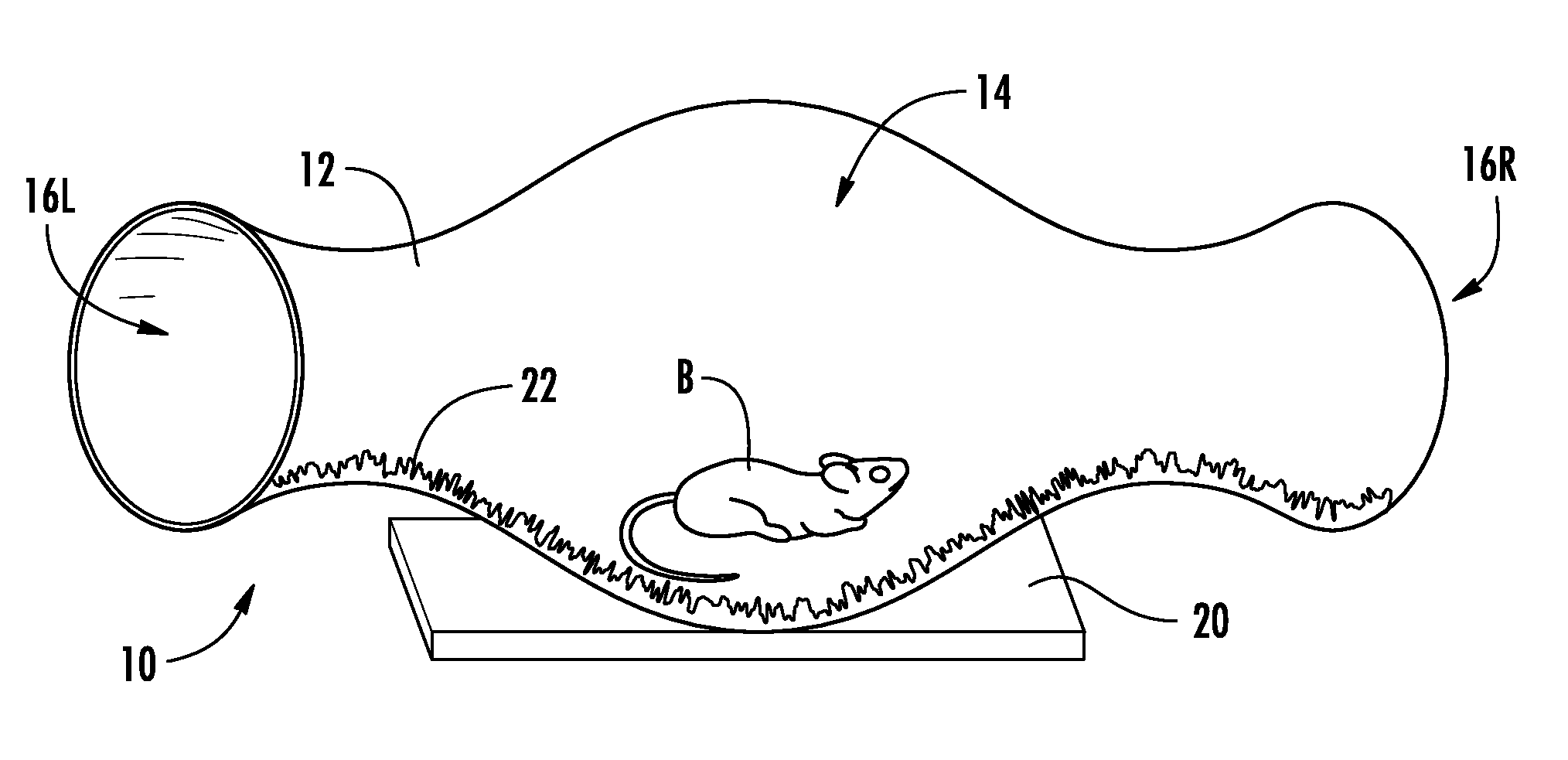
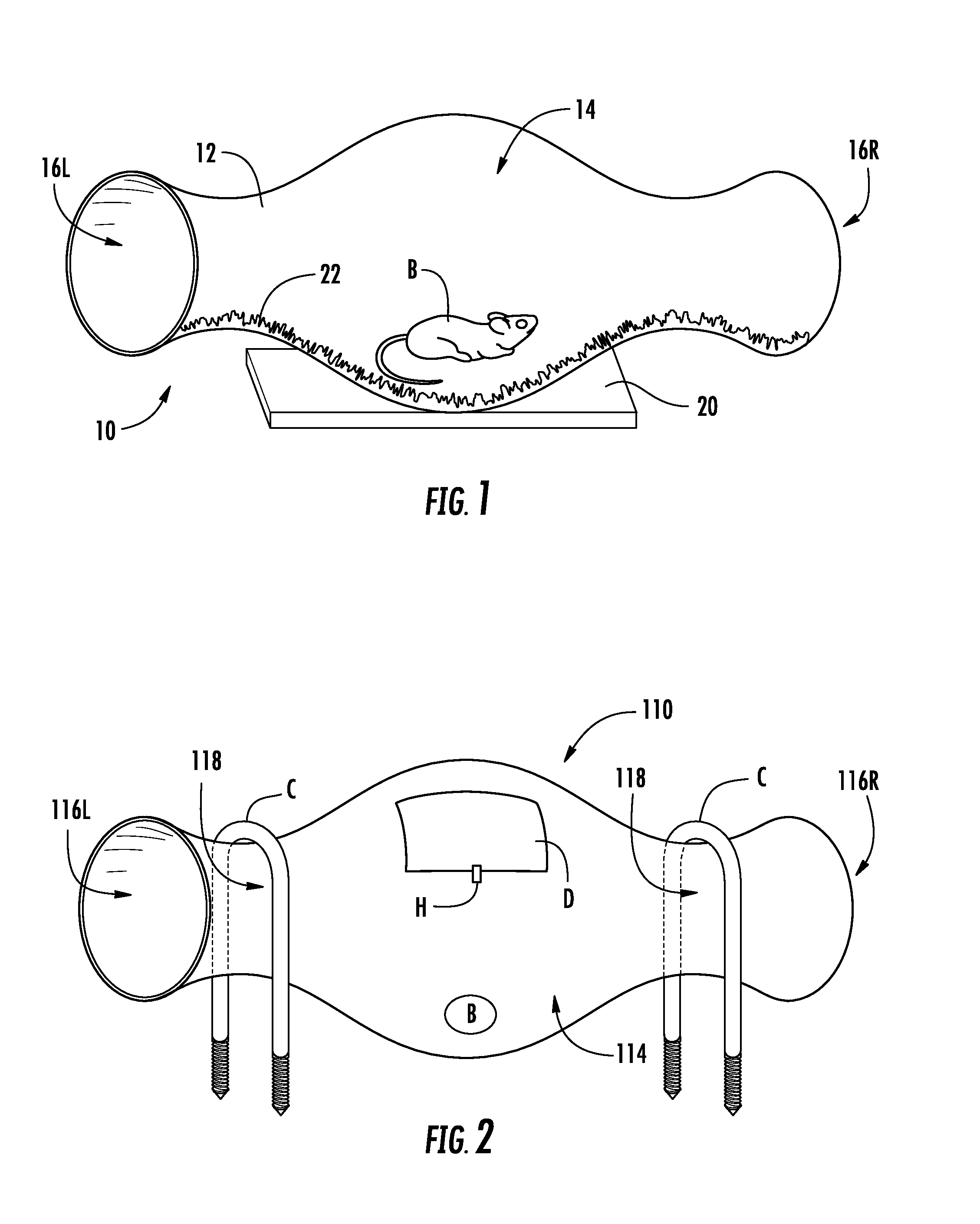
[0017]In FIG. 1, a first embodiment of snake trap is shown. In subsequent alternate embodiments, common components are consistently numbered through in the next hundred series. This invention, known as the Snake Killer™, is a trap for catching and killing snakes. The trap, generally 10, is meant to safely “hold” poisonous bait B inside a casing, containment or other elongated tubular housing 12 that only the targeted snake will be able to access. A snake will die after entering trap 10 and swallowing the poisonous bait B. However, it will NOT allow accidental access by family pets, children or the like.

[0018]The bait to be used with this invention may resemble many objects like a mouse, rat, other small mammal, reptile, salamander, etc. It will also work with baited poisonous eggs.

[0019]The housing 12 (or case) should be clear and made or plastic or a hardened glass. One embodiment has the shape of a hurricane lamp (i.e., with a thicker belly or middle section 14) and additionally b...


PUM


Abstract

There is claimed a snake trap comprising an elongated tube having two open ends with a larger circumference middle section or belly into which is placed poisonous bait for consumption by the snake that enters. Preferably, it is clear and made of plastic or glass with camouflage type decorations for resembling grass, sand or garden-like appearances. A locking access door may be included and an optional carrying handle. Optionally, each open end can be fitted with directional guards for discouraging a snake from exiting the trap once it has entered the same.

Description

CROSS-REFERENCE TO RELATED APPLICATIONS[0001]This is a continuation-in-part of application Ser. No. 14 / 544,013, filed on Nov. 14, 2014, which is a perfection of Provisional Application No. 62 / 026,684, filed on Jul. 20, 2014, both disclosures of which are fully incorporated by reference herein.FIELD OF THE INVENTION[0002]The present invention pertains to snake killing and related traps. More particularly, it relates to a snake trap with an area for holding for holding poisonous bait that only the snake can access.[0003]Snakes can generate fear and cause injury to people and animals. It would be a benefit, therefore, to have a snake trap that could be used to trap and dispose of. Alternately, this trap can dispense poisonous bait that the snake can digest and then die elsewhere.[0004]Known traps for snakes and other animals include those set forth in: Slauth U.S. Pat. No. 2,573,228, Otterson U.S. Pat. No. 4,244,134, Smith U.S. Pat. No. 4,763,439, Henning U.S. Pat. No. 5,067,271 and Fo...

Claims


Application Information

Patent Timeline
IPC IPC(8): A01M25/00A01M23/00
CPCA01M23/00A01M25/004A01M23/08
Inventor GREEN, ANDRE
Owner GREEN ANDRE
Why Eureka
Try Eureka