
Apparatus and method for treating perfluoro-compound

a technology of perfluorocompounds and apparatuses, applied in the field of apparatus and methods for treating perfluorocompounds, can solve problems such as global warming

Inactive Publication Date: 2013-10-24
GLOBAL STANDARD TECH
View PDF5 Cites 5 Cited by
  • Summary
  • Abstract
  • Description
  • Claims
  • Application Information

AI Technical Summary

Benefits of technology

The present invention describes an apparatus designed to remove perfluoro compounds from exhaust gases released by industrial facilities located outside buildings. This device allows for larger scale purification of these harmful chemicals.

Problems solved by technology

The technical problem addressed by this patent is how to effectively use PFC-based gases for etching, cleaning, or deposition processes during LCD or OLED production while reducing harmful effects on the environment caused by global warming. A purification process is needed to remove impurities from the released gases prior to their introduction into the atmosphere.

Method used


Image

  • Apparatus and method for treating perfluoro-compound
  • Apparatus and method for treating perfluoro-compound
  • Apparatus and method for treating perfluoro-compound

Examples


example

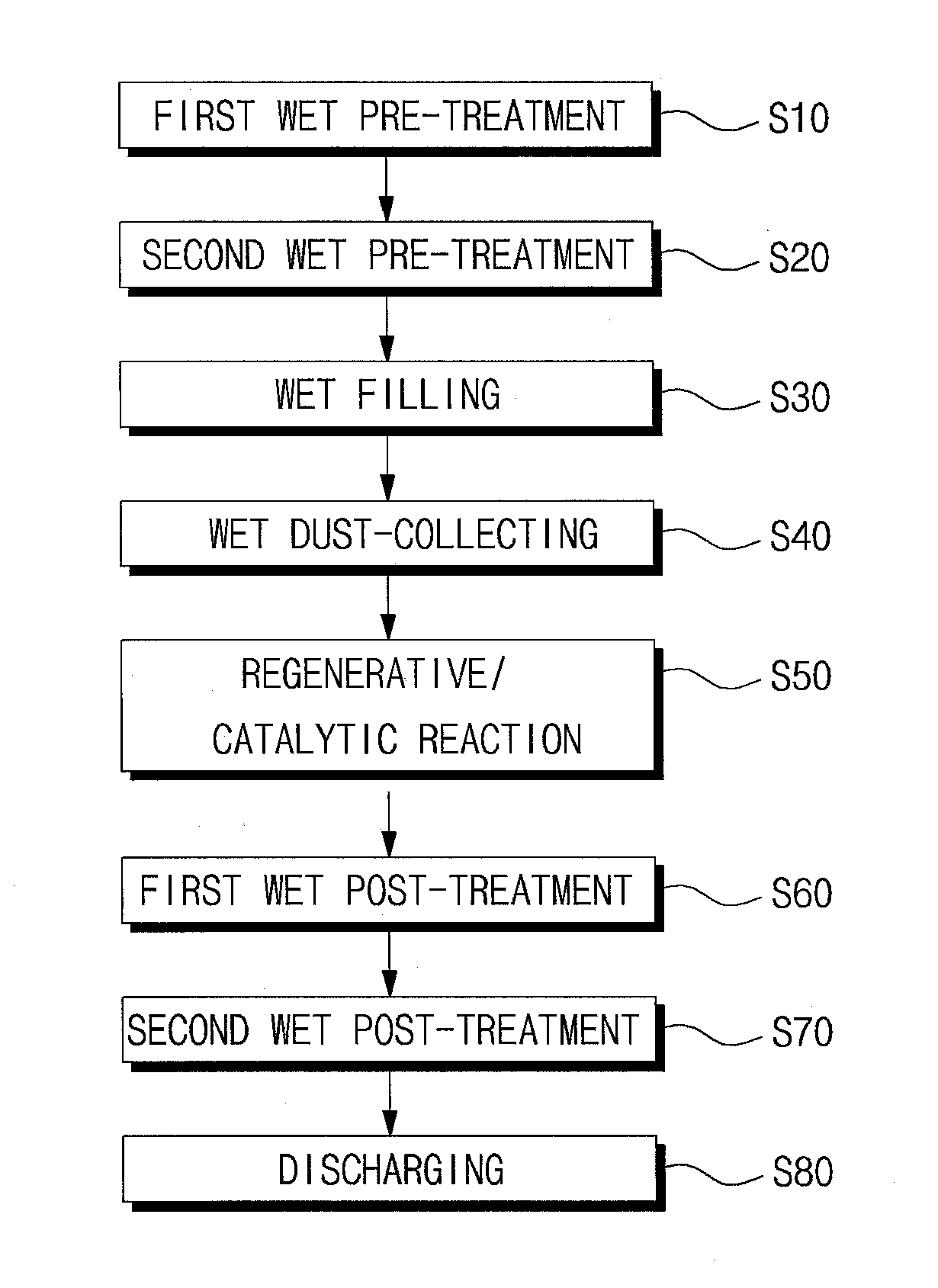
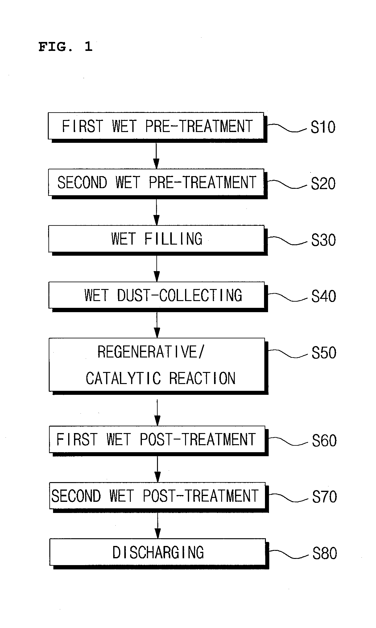
[0031]FIG. 1 is a flow chart showing a method for treating a perfluoro-compound according to one embodiment of the present invention. Referring to FIG. 1, the treatment method for perfluoro-compounds (PFCs) is directed to a method of purifying PFCs contained in an exhaust gas emitted from, for example, a semiconductor manufacturing device.

[0032]The PFCs are used in the etching, cleaning, or deposition process of the semiconductor processing and may include any one processing gas, such as, for example, CF4, SF6, NF3, C2F6, C3F8, CHF3, etc.

[0033]The treatment method for PFCs comprises a first wet pre-treatment step S10, a second wet pre-treatment step S20, a wet filtering step S30, a wet dust-collecting step S40, a regenerative / catalytic reaction S50, a first wet post-treatment step S60, a second wet post-treatment step S70, and a discharging step S80, which steps S10 to S80 are sequentially conducted in succession.

[0034]In the first wet pre-treatment step S10, PFCs contained in the e...


PUM

PropertyMeasurementUnit
Temperatureaaaaaaaaaa
Areaaaaaaaaaaa

Abstract

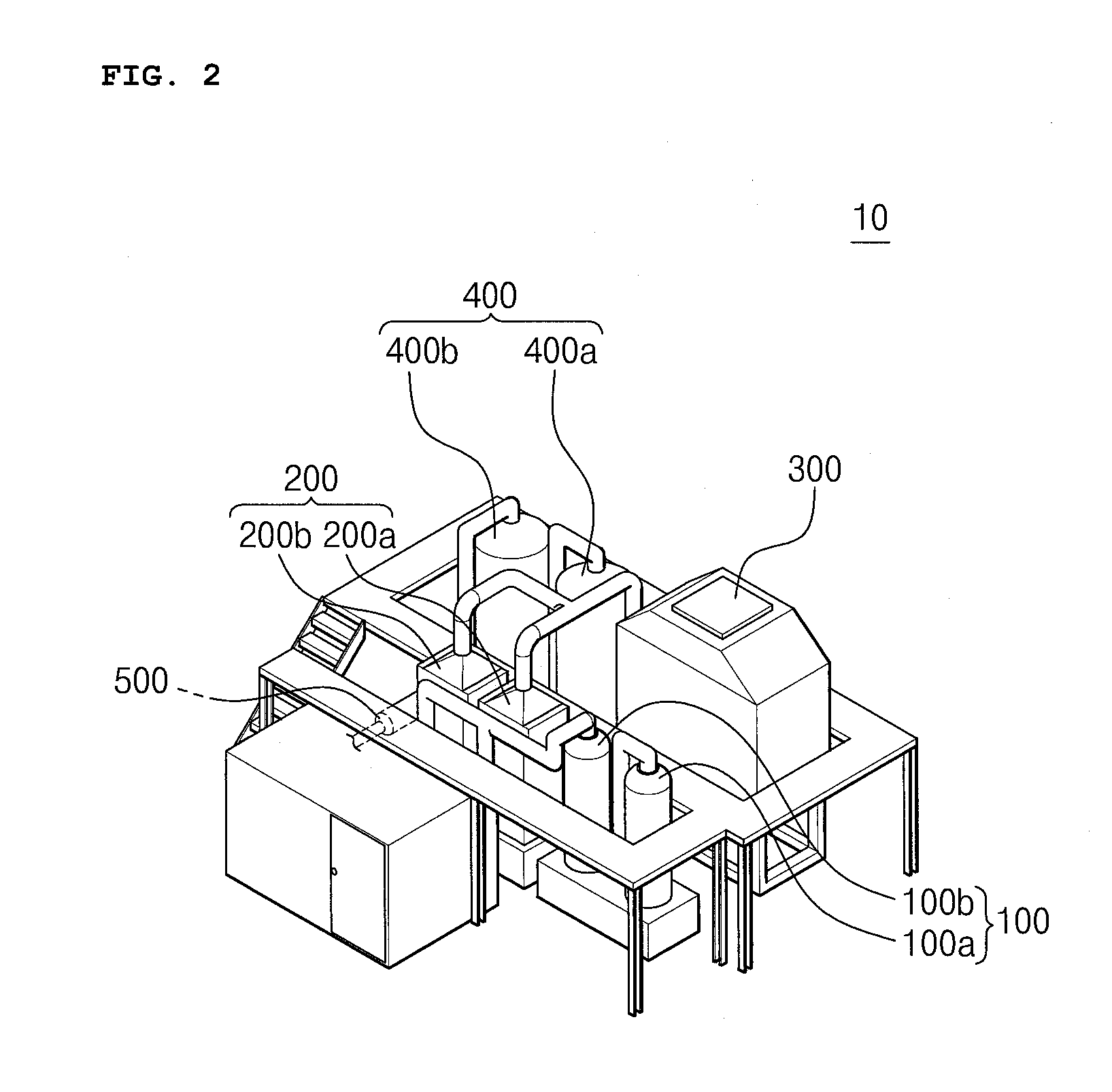
The present invention discloses an apparatus and method for treating perfluoro-compounds (PFCs). The method for treating PFCs includes: (a) decomposing PFCs and eliminating a first acid gas generated by the decomposition through a pre-cleaner; (b) filtering out dust particles from the exhaust gas through a filter; (c) electrifying the dust particles in the exhaust gas by electrical discharge and collecting dusts through a dust collector; (d) decomposing PFCs using a regenerative/catalytic reaction through a catalytic reactor; (e) eliminating a second acid gas generated by the regenerative/catalytic reaction through a post-cleaner; and (f) letting the purified exhaust gas out through a fan.

Description


Claims


Application Information

Patent Timeline
Owner GLOBAL STANDARD TECH
Learn More