Supercharge Your Innovation With Domain-Expert AI Agents!

Method for Working Structural Members

a structural member and work method technology, applied in the field of finished article fabrication, can solve the problem that the operation will typically take a number of hours

Inactive Publication Date: 2013-10-24
FITZGERALD KEVIN FRANCIS +1
View PDF10 Cites 2 Cited by
  • Summary
  • Abstract
  • Description
  • Claims
  • Application Information

AI Technical Summary

Benefits of technology

The present invention provides a computer-controlled method for fabricating articles from a digital information source, which includes extracting data from the source, determining tasks to be performed on the primary members to transform them into the articles, and transmitting a sequence of commands to the fabrication machine for carrying out the tasks on the primary members. The method may include checking the correctness of the primary member or secondary members, confirming the camber of the member, checking the end of the member, and confirming the identity of the primary member or secondary members. The invention also provides a computer software product and computer program for carrying out the method.

Problems solved by technology

These operations will typically take a number of hours.

Method used


Image

  • Method for Working Structural Members
  • Method for Working Structural Members
  • Method for Working Structural Members

Examples


Embodiment Construction

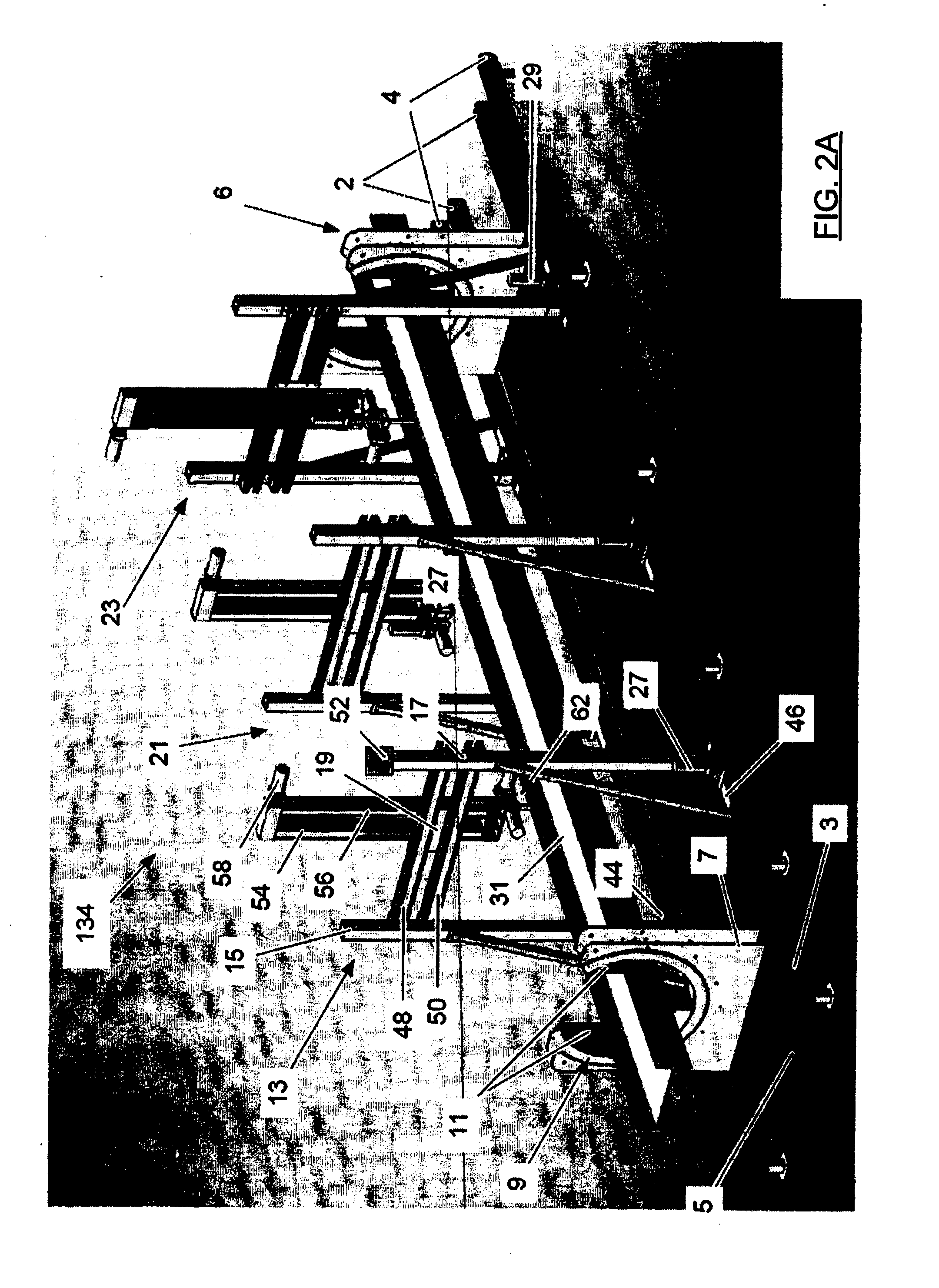
[0064]Referring now to FIG. 2A, there is depicted a beam fabrication machine 134 for working on steel members which may be variously referred to as the “Ironman” in the following description.

[0065]The beam fabrication machine 134 is shown loaded with a work piece in the form of a steel beam 31.

[0066]Fabrication machine 134 includes an inner pair of rails 2, and an outer pair of rails 4. Two rotatable vises, 9 and 6 ride along the inner pair of rails 2. FIGS. 2B, 2C and 2G show vise 9 in greater detail.

[0067]The arrangement of vise 6 corresponds to that of vise 9 which will now be described with reference to FIGS. 2B and 2C. The vise 9 is comprised of a stand in the form of an opposing pair of plates 7, 8 interconnected by bearing rollers 16 which are disposed in an arc about corresponding central arcuate cutouts formed through each plate. The bearing rollers support an arcuate cradle 18 that is located within the cutout and is flanged with opposing arcuate flanges 22 and 24 that ove...


PUM


Abstract

A computer supervised method if provided for fabricating articles defined in an electronic information source. The method is performed with a computer in communication with a computer controllable steel fabrication machine of a type that includes vises for holding and rotating a primary member of the article, for example a steel beam, under control of the computer. The method includes operating the computer to extract data from the information source including data defining primary members corresponding to each article. The computer then determines tasks be performed on the primary members by the fabrication machine to transform the primary members, e.g. steel beams, into the articles. The computer transmits a sequence of commands to the machine for carrying out the tasks on the primary members to thereby fabricate the articles.

Description

TECHNICAL FIELD[0001]The present invention relates to a method for fabricating finished articles from structural members. In a preferred embodiment there is provided a method for fabricating structural articles such as finished steel beams by means of a computer controlled fabrication machine.BACKGROUND[0002]The discussion of any prior art documents, techniques, methods or apparatus is not to be taken to constitute any admission or evidence that such prior art forms, or ever formed, part of the common general knowledge.[0003]Structural members are commonly used in the building industry. Steel fabrication involves welding and cutting steel members, such as U-Beams, according detailed drawings. For example, FIG. 1 depicts a finished structural steel article 102 formed from a primary member in the form of a universal beam (“U-Beam”) 104.[0004]The U-Beam 104 has been operated upon to incorporate a number of features according to a detailed shop drawing. The U-Beam has had notches 112 cu...

Claims


Application Information

Patent Timeline
Patent Type & Authority Applications(United States)
IPC IPC(8): G05B15/02
CPCG05B15/02G05B19/4097G05B19/41805Y02P90/02B23Q15/00B23Q35/00B23Q39/00B23P23/00
Inventor FITZGERALD, KEVIN FRANCISCHALLEN, NATHAN
Owner FITZGERALD KEVIN FRANCIS
Features
  • R&D
  • Intellectual Property
  • Life Sciences
  • Materials
  • Tech Scout
  • Unparalleled Data Quality
  • Higher Quality Content
  • 60% Fewer Hallucinations
Learn More