Method For Controlling Movement Of Travelling Carriers

Active Publication Date: 2013-10-24
DAIFUKU CO LTD
View PDF4 Cites 1 Cited by
  • Summary
  • Abstract
  • Description
  • Claims
  • Application Information

AI Technical Summary

Benefits of technology

The present invention provides a method for controlling movement of carriers within a work area without the need for a communication means to be laid under the carriers throughout the work area. This saves time, money, and allows for easy changes in work area layout. The method uses a movement permission signal sent from a ground-based communication means at one end of the work area to all the carriers within the work area. The data communication between carriers is performed through an optical communication means, which is inexpensive and easy to maintain. The method ensures reliable movement control and efficient data communication within the work area.

Problems solved by technology

Furthermore, the means to transmit the movement permission signal to all of the travelling carriers within the work area performs data communication between front and rear two adjacent travelling carriers, so that a data communication path of which one unit of the data communication means takes charge becomes remarkably short linearly.

Method used


Image

  • Method For Controlling Movement Of Travelling Carriers
  • Method For Controlling Movement Of Travelling Carriers
  • Method For Controlling Movement Of Travelling Carriers

Examples


Embodiment Construction

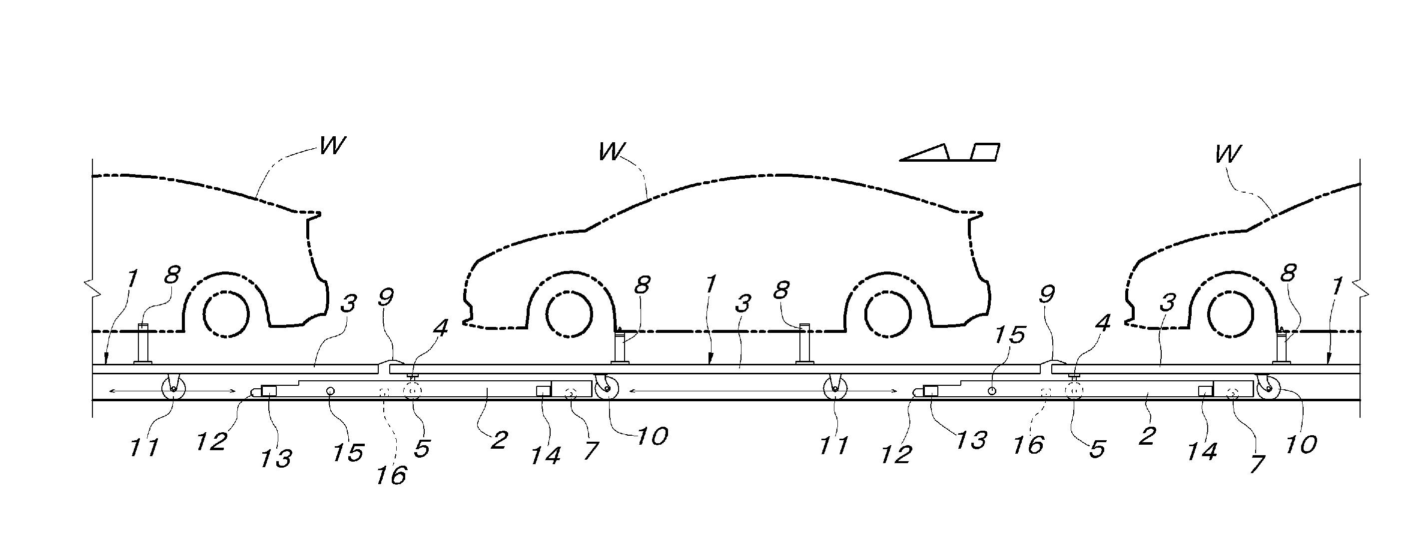
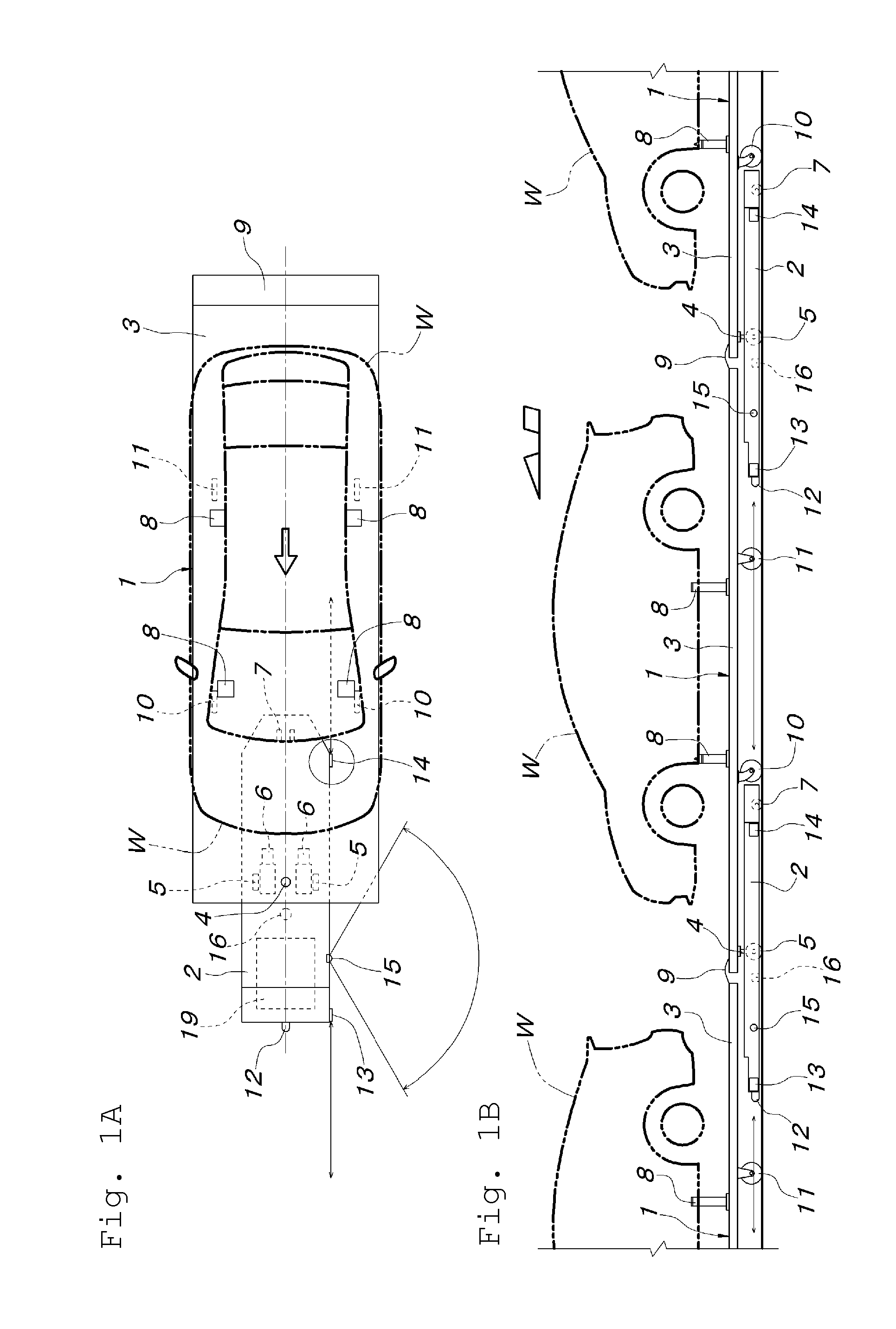
[0020]As shown in FIG. 1, a travelling carrier 1 employed in this embodiment consists of a combination of a self-propelled tractor 2 and a conveying carriage 3 towed by the tractor 2. The tractor 2 has such a low-floor structure that the vehicle height thereof is low enough to move under the conveying carriage 3. While a rear half of the tractor 2 is entered under a front end of the conveying carriage 3, the vicinity of a longitudinal center of the tractor 2 and the vicinity of a width center near the front end of the conveying carriage 3 are connected by a vertical connecting shaft 4 so as to be relatively rotatable about the vertical connecting shaft 4. The tractor 2 is provided with a pair of left and right driving wheels 5 positioned at both lateral sides of the vertical connecting shaft 4, a pair of left and right motors 6 respectively driving and rotating the both driving wheels 5 in any of normal and reverse directions, and a rear wheel 7 positioned at the width center near t...


PUM


Abstract

A method for controlling movement of travelling carriers includes performing data communication between front and rear adjacent travelling carriers, an on-board communication device provided to the travelling carrier and performing data communication with a ground-based communication device, and the ground-based communication device sending a movement permission signal at one end of a work area to the on-board communication device of a passing travelling carrier; and transmitting the movement permission signal to all of the travelling carriers within the work area from the ground-based communication device via the on-board communication device and the data communication means.

Description

FIELD OF THE INVENTION[0001]The present invention relates to a method for controlling movement of self-propelled travelling carriers to have the travelling carriers move on their own at a fixed low operating speed within a work area while keeping a state that the travelling carries are continuous in a moving direction.BACKGROUND OF THE INVENTION[0002]In an automobile assembly line, a work area is used where self-propelled travelling carriers loaded with vehicle bodies are moved at a fixed low operating speed with respective work floors thereof being continuous in a moving direction and at the same time required operations are performed on the loaded vehicle bodies. On the occasion when the self-propelled travelling carriers are moved on their own in such a work area, a movement permission needs to be given from the ground to all of the travelling carriers within the work area and the moving at the operating speed needs to be continued during the period when the movement permission i...

Claims


Application Information

Patent Timeline
IPC IPC(8): G05D1/02
CPCG05D1/028B62D65/18
Inventor YOKOTA, TOSHIAKIMIYOSHI, KAZUHIKOKAMEI, MASATSUGUISEKI, ATSUNOBU
Owner DAIFUKU CO LTD
Why Eureka
Try Eureka