Vehicle drive device

a technology of drive device and drive shaft, which is applied in the direction of gearing details, gearing, transportation and packaging, etc., can solve the problems of affecting the lubrication of the appropriate lubrication, and affecting the axial dimension of the entire device. , to achieve the effect of smooth supply

Inactive Publication Date: 2013-10-31
AISIN AW CO LTD +1
View PDF4 Cites 57 Cited by
  • Summary
  • Abstract
  • Description
  • Claims
  • Application Information

AI Technical Summary

Benefits of technology

[0028]According to the configuration, the oil pump can be driven utilizing a drive force of the internal combustion engine, which is drivably coupled to the input shaft, to supply oil to the inside housing space via the in-shaft oil passage and the supply communication oil passage. On the other hand, as discussed above, oil is supplied to the inside housing space via the oil reserving portion, the communication oil passage, the inner circumferential space, and the supply communication hole irrespective of rotation of the internal combustion en

Problems solved by technology

Such an arrangement causes the ring gear, the output bearing, and the sleeve-like member (14) to occupy a large space in the axial direction in the device, which disadvantageously increases

Method used


Image

  • Vehicle drive device
  • Vehicle drive device
  • Vehicle drive device

Examples


Embodiment Construction

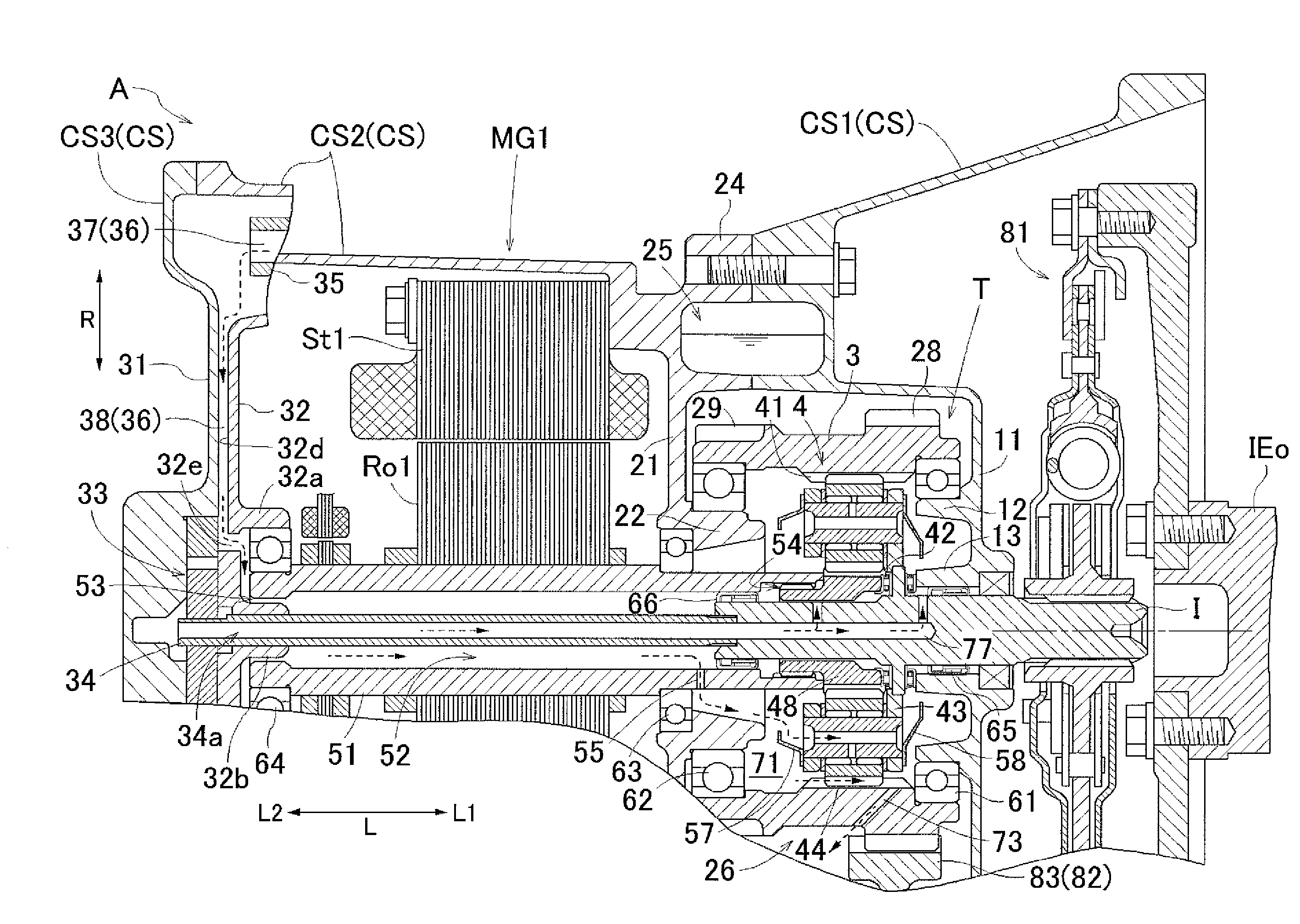
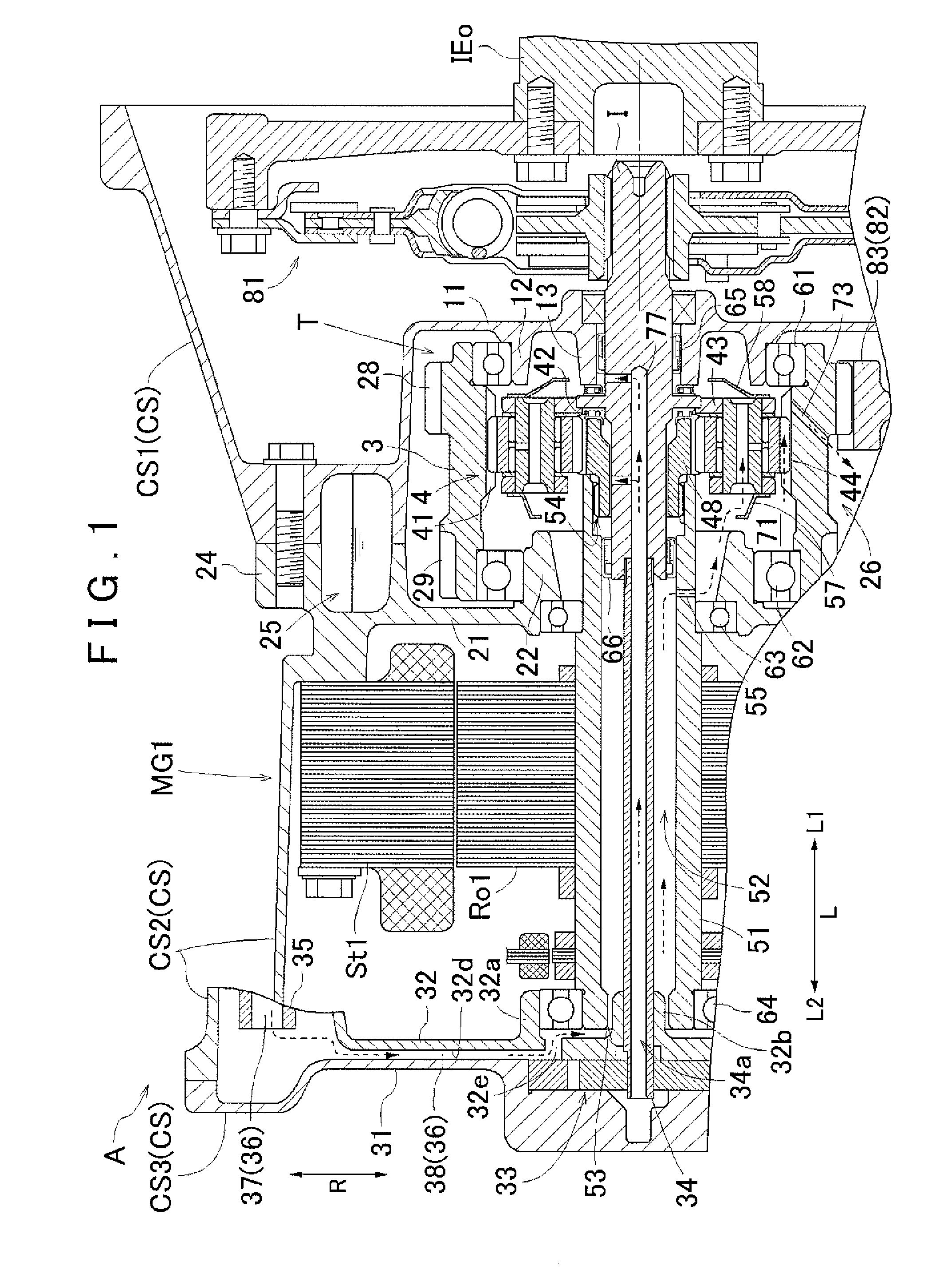
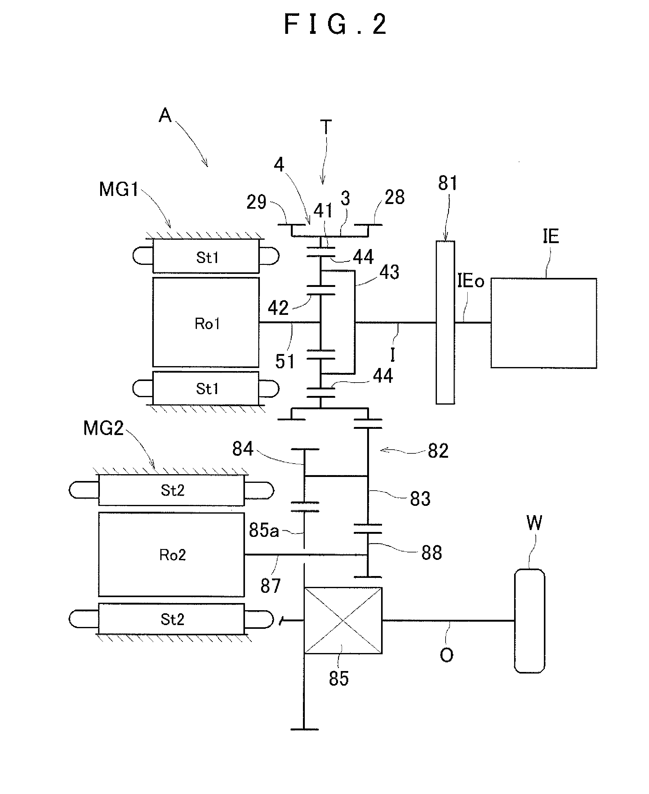
[0038]A vehicle drive device according to an embodiment of the present invention will be described with reference to the drawings. The vehicle drive device is a drive device for use for a hybrid vehicle including an internal combustion engine and at least one rotary electric machine as drive force sources for wheels. In the embodiment, a vehicle drive device A is formed as a drive device for a so-called two-motor split type hybrid vehicle including an internal combustion engine IE and two rotary electric machines MG1 and MG2 as drive force sources for wheels W. That is, the vehicle drive device A includes an input shaft I drivably coupled to the internal combustion engine IE, a first rotary electric machine MG1 disposed coaxially with the input shaft I, a second rotary electric machine MG2, an output shaft O drivably coupled to the wheels W, and a power transfer mechanism T that drivably couples the input shaft I, the first rotary electric machine MG1, and the output shaft O. These ...


PUM


Abstract

A vehicle drive device configured with reduced axial dimensions, while still having appropriate lubrication. The vehicle drive device is configured with an input shaft coupled to an engine, a rotary electric machine, and an output shaft coupled to wheels. A power transfer mechanism couples input shaft, the rotary electric machine, and the output shaft. A case houses at least the rotary electric machine and the power transfer mechanism. An oil reserving portion capable of reserving oil supplied by rotation of the power transfer mechanism is provided above the rotor shaft inside the case. A communication oil passage is oriented between the oil reserving portion and an inner circumferential space formed inside the rotor shaft. The rotor shaft is disposed to be inserted into the inside housing space, and has a supply communication hole that communicates between the inner circumferential space and the inside housing space.

Description

INCORPORATION BY REFERENCE[0001]The disclosure of Japanese Patent Application No. 2011-022839 filed on Feb. 4, 2011 including the specification, drawings and abstract is incorporated herein by reference in its entirety.BACKGROUND OF THE INVENTION[0002]The present invention relates to a vehicle drive device including an input shaft drivably coupled to an internal combustion engine, a rotary electric machine, an output shaft drivably coupled to wheels, a power transfer mechanism that drivably couples the input shaft, the rotary electric machine, and the output shaft, and a case that houses at least the rotary electric machine and the power transfer mechanism.DESCRIPTION OF THE RELATED ART[0003]A device disclosed in Japanese Patent Application Publication No. 2000-217205 (JP 2000-217205 A) mentioned below is already known as an example of the vehicle drive device described above. In the following description in the Description of the Related Art section, reference numerals and names us...

Claims


Application Information

Patent Timeline
IPC IPC(8): F16H37/06F16H57/04B60L50/16
CPCF16H37/065F16H57/043Y10S903/902B60K6/405B60K6/445F16H57/0424F16H57/0479F16H57/0486F16H3/727F16H2037/0866F16H2200/2005B60K6/365B60K6/48B60K2006/4825B60K2006/4833Y10T74/19056Y02T10/62B60K6/22B60K6/26F16H1/28
Inventor YAMAMOTO, YOSHIHISASENO, MASAMITSUKOMATSU, TAKUYASADA, NATSUKIYATA, HIROTAKAATARASHI, TOMOOKIMURA, HIROMICHIKUWAHARA, TAKESHIOBATA, TATSUOTSUCHIDA, MICHITAKAMORITA, YOSHINORIKATO, SHINGO
Owner AISIN AW CO LTD
Why Eureka
Try Eureka