Circuit breaker

a circuit breaker and circuit breaker technology, applied in the field of circuit breaker, can solve problems such as difficulty in breaking, and achieve the effect of improving the breaking performance of circuit breaker and reducing the size of circuit breaker

Inactive Publication Date: 2013-10-31
FUJI ELECTRIC FA COMPONENTS & SYST CO LTD
View PDF3 Cites 49 Cited by
  • Summary
  • Abstract
  • Description
  • Claims
  • Application Information

AI Technical Summary

Benefits of technology

[0028]According to the contact breaker in the invention, as the electromagnetic force acts on the arc by the magnetic flux generated by the permanent magnets, the arc moves to the grid base portion side, and the arc contacting with the magnetic grids of the arc extinguishing device is split up, cooled, and quickly extinguished, and it is thus possible to improve the breaking performance of the circuit breaker, even when it is used in ...

Problems solved by technology

When connecting this kind of circuit breaker to a direct current circuit, as an arc is generated when breaking the direct current c...

Method used


Image

  • Circuit breaker
  • Circuit breaker
  • Circuit breaker

Examples


Embodiment Construction

[0038]Hereafter, a detailed description will be given, while referring to the drawings, of an aspect (hereafter referred to as an embodiment) for implementing the invention.

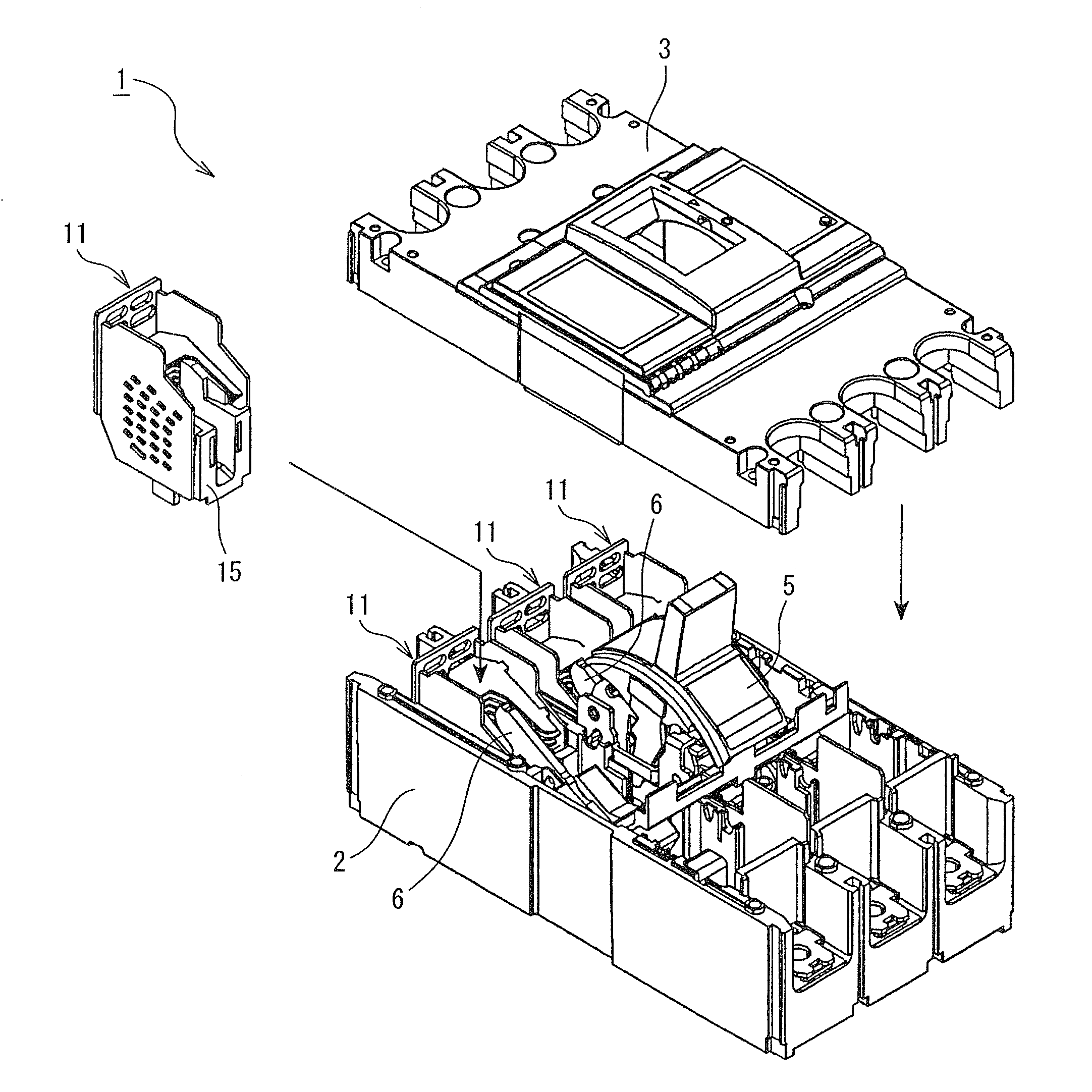
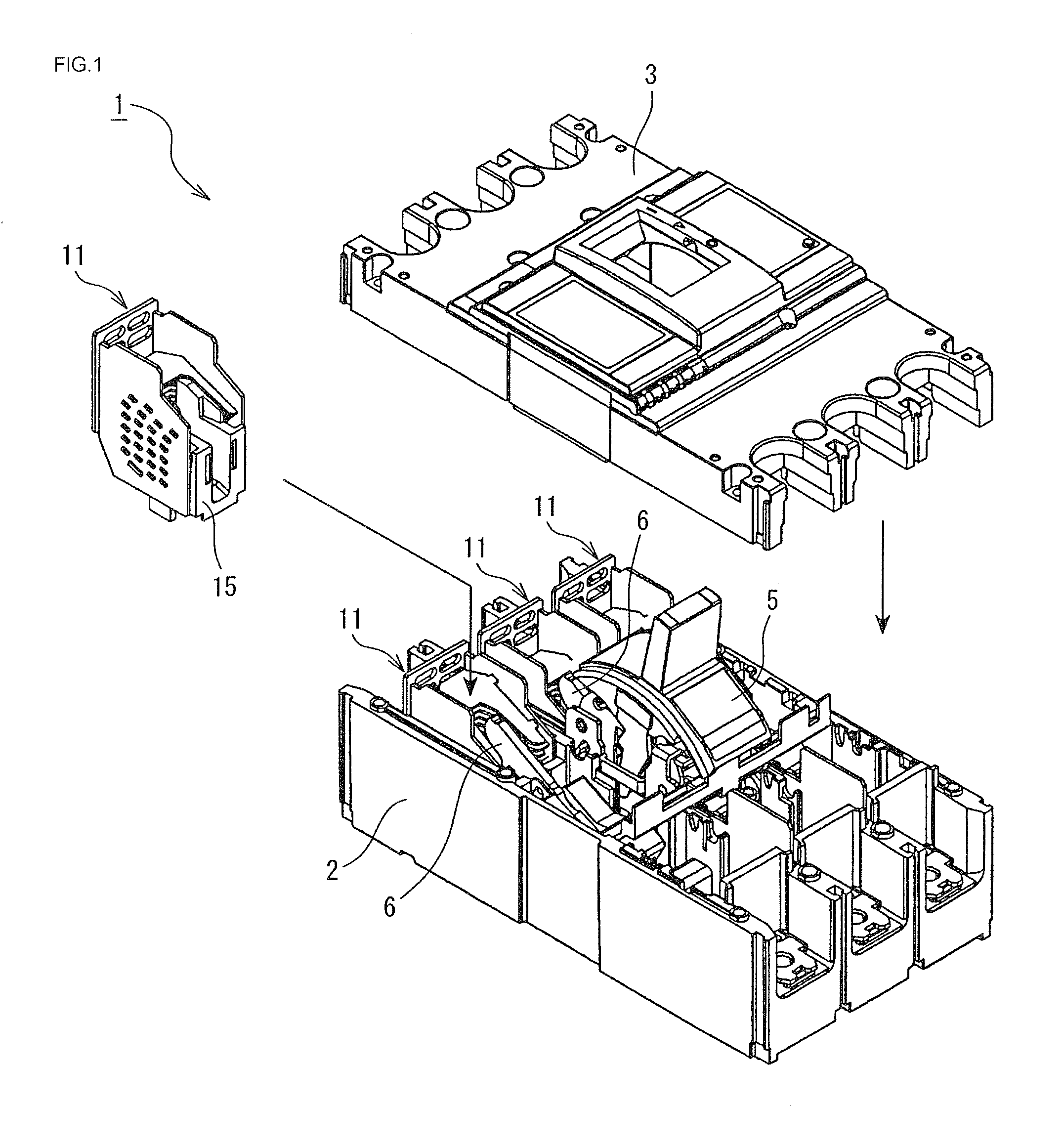
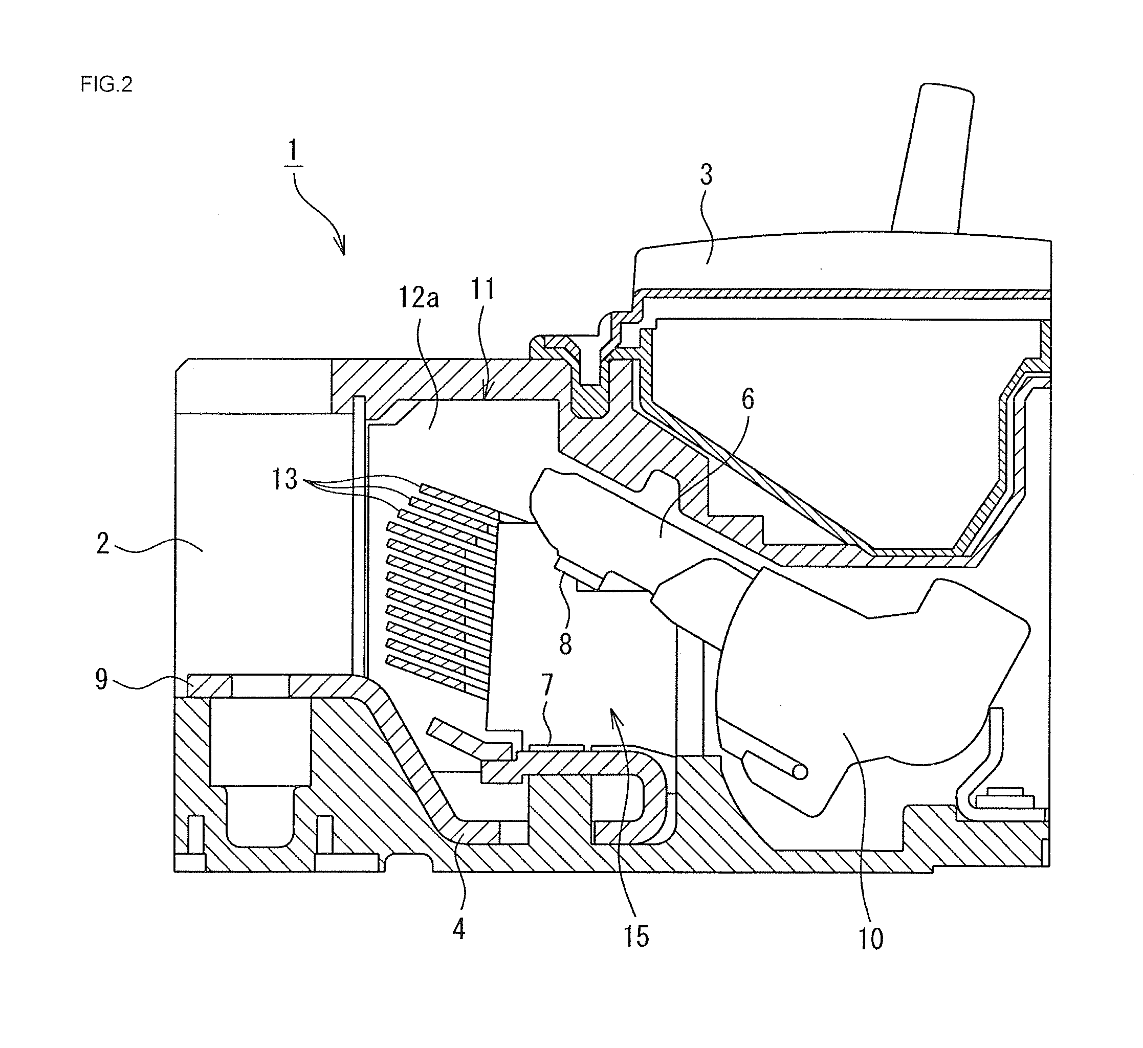
[0039]FIG. 1 is an exploded perspective view showing components of a three-pole circuit breaker (hereafter called a circuit breaker) 1 according to the invention, while FIG. 2 is a longitudinal sectional view of a main portion of the circuit breaker 1.

[0040]The circuit breaker 1 of the embodiment is such that a breaker unit formed of a fixed contact 4 fixed to a case 2 and a movable contact 6 driven so as to open and close by a switching mechanism 5 is provided inside an insulating receptacle formed of the case 2 and a cover 3, as shown in FIG. 1.

[0041]As shown in FIG. 2, the fixed contact 4 has a fixed contact point 7 at one end, while a power source side terminal 9 is integrally formed with the other end.

[0042]The movable contact 6 has a movable contact point 8 at one end, the movable contact point 8 contacting...


PUM


Abstract

A circuit breaker includes a fixed contact having a fixed contact point; a movable contact having a movable contact point contacting with the fixed contact point; and an arc extinguishing device housed in a main body case. In the arc extinguishing device, a plurality of magnetic grids, each having a pair of grid leg portions, is disposed in layer form, and an arc generated between the fixed contact point and the movable contact point at a time of an opening operation is drawn into the magnetic grids and extinguished. A magnetic flux is generated between the pairs of grid leg portions configuring the arc extinguishing device in a direction perpendicular to the arc generated between the fixed contact point and the movable contact point, and permanent magnets and a permanent magnet holding member are disposed therein.

Description

TECHNICAL FIELD[0001]The present invention relates to a circuit breaker, which is optimal for a high voltage direct current circuit.BACKGROUND ART[0002]In order to interrupt an overcurrent in a short circuit current or overload current, flowing through a load circuit, a circuit breaker such as a wiring breaker or earth leakage breaker is used.[0003]The circuit breaker is such that, when a movable contact carries out an operation of contacting with or separating from a fixed contact to carry out an opening and closing of a main circuit, an arc generated between a fixed contact point of the fixed contact and a movable contact point of the movable contact is extinguished in an arc extinguishing device.[0004]The arc extinguishing device includes a plurality of grids formed in a U-shape or V-shape and a pair of side plates that supports the plurality of grids, which is disposed in a stacked condition with gaps, and is disposed so as to enclose the movement trajectory of the movable conta...

Claims


Application Information

Patent Timeline
IPC IPC(8): H01H33/18
CPCH01H33/182H01H9/302H01H9/346H01H9/36H01H9/443H01H73/18
Inventor HAMADA, YOSHINOBUKIMISHIMA, YOSHIYUKIYONEMITSU, KAZUNORIONCHI, TOSHIYUKIYAMAUCHI, HOUJYUN
Owner FUJI ELECTRIC FA COMPONENTS & SYST CO LTD
Why Eureka
Try Eureka