
Apparatus and method for controlling a plurality of power converting modules and apparatus and method for analyzing power quantity imbalance

a power converting module and apparatus technology, applied in the direction of power conversion systems, dc-dc conversion, instruments, etc., can solve the problems of difficult to guarantee the same lifetime to several modules constituting the complex type power converting device of the module, corresponding modules may be broken, and the module may be broken, so as to achieve accurate detection and easy identification

Active Publication Date: 2013-10-31
KOREA INST OF ENERGY RES
View PDF20 Cites 12 Cited by
  • Summary
  • Abstract
  • Description
  • Claims
  • Application Information

AI Technical Summary

Benefits of technology

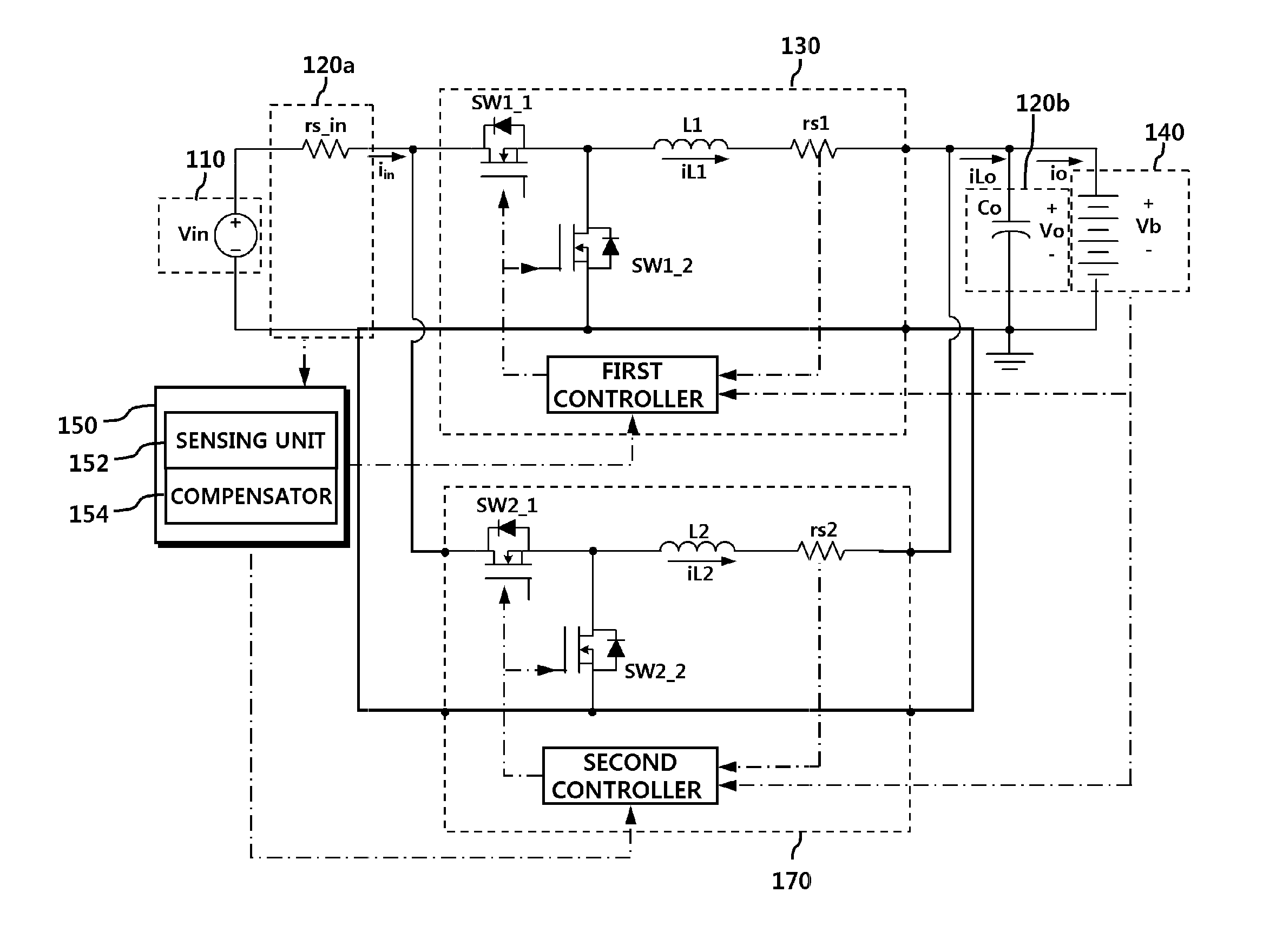
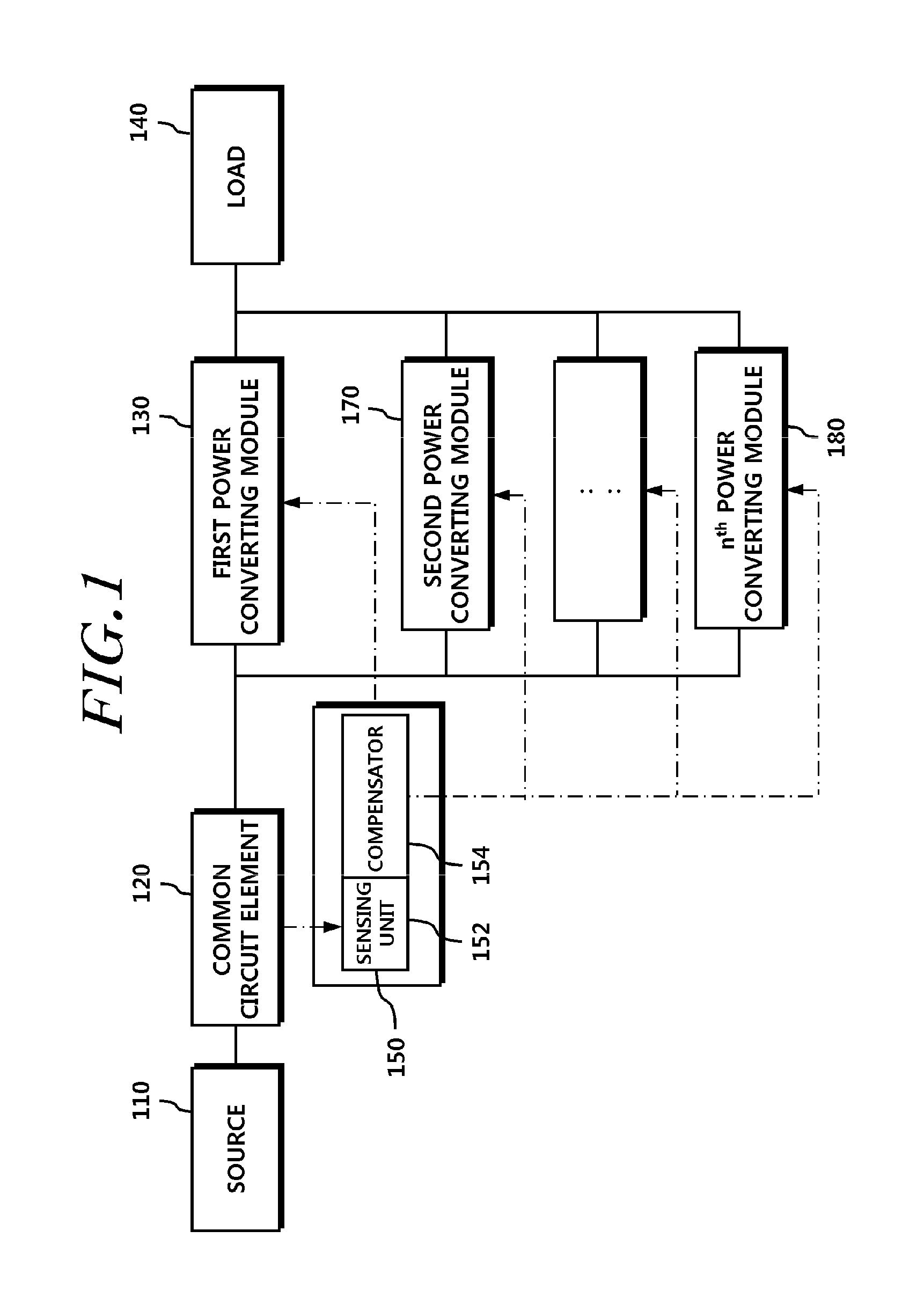
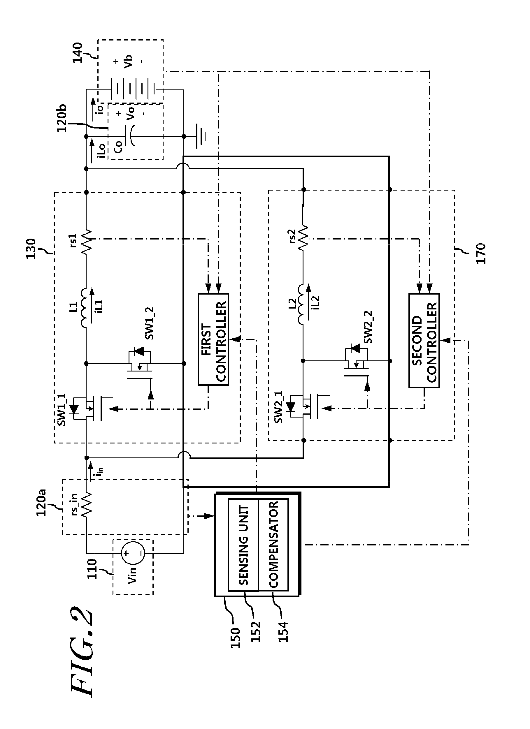
The present invention is about a power converting device that can detect and analyze the difference in power quantities processed by multiple modules. This is achieved by using a common circuit element shared by the modules to detect relative power quantities instead of relying on individual sensors in each module. This approach allows for more accurate detection of power imbalances and easier identification by a manager. The invention compensates for the imbalances by sharing control values among the modules.

Problems solved by technology

According to demands for standardization of power converting devices, a lot of module complex type power converting devices for converting power as much as desired by using several power converting modules in parallel have been developed.
One problem of the module complex type power converting device is that it is difficult to guarantee the same lifetime to several modules constituting the module complex type power converting device.
The corresponding module may be broken due to a problem occurring in only one component mounted to one module or only the corresponding module may be broken due to a problem such as overloads occurring in one module.
However, in a particular case, entire modules may become useless since required power is not converted.

Method used


Image

  • Apparatus and method for controlling a plurality of power converting modules and apparatus and method for analyzing power quantity imbalance
  • Apparatus and method for controlling a plurality of power converting modules and apparatus and method for analyzing power quantity imbalance
  • Apparatus and method for controlling a plurality of power converting modules and apparatus and method for analyzing power quantity imbalance

Examples


Embodiment Construction

[0027]Hereinafter, exemplary embodiments of the present invention will be described with reference to the accompanying drawings. In the following description, the same elements will be designated by the same reference numerals although they are shown in different drawings. Further, in the following description of the present invention, a detailed description of known functions and configurations incorporated herein will be omitted when it may make the subject matter of the present invention rather unclear.

[0028]In addition, terms, such as first, second, A, B, (a), (b) or the like may be used herein when describing components of the present invention. Each of these terminologies is not used to define an essence, order or sequence of a corresponding component but used merely to distinguish the corresponding component from other component(s). It should be noted that if it is described in the specification that one component is “connected,”“coupled” or “joined” to another component, a t...


PUM


Abstract

Disclosed is a technology related to an apparatus for controlling or analyzing a power converting module, and more particularly, to a technology for improving imbalance of power quantities processed by a plurality of power converting modules. Relative power quantities processed by the modules are detected through a common circuit element installed in an input terminal or an output terminal shared by the plurality of modules, without detecting information acquired through current or voltage sensors individually installed in respective modules, and control values of the respective modules may be compensated for through the detected relative power quantities or may be output in a form where a user can easily identify them.

Description

CROSS-REFERENCE TO RELATED APPLICATION[0001]This application claims priority from and the benefit under 35 U.S.C. §119(a) of Korean Patent Application No. 10-2012-0043393, filed on Apr. 25, 2012, which is hereby incorporated by reference for all purposes as if fully set forth herein.BACKGROUND OF THE INVENTION[0002]1. Field of the Invention[0003]The present invention relates to an apparatus for controlling or analyzing a power converting module, and more particularly to a technology for improving an imbalance of power quantities processed by a plurality of power converting modules.[0004]2. Description of the Prior Art[0005]According to demands for standardization of power converting devices, a lot of module complex type power converting devices for converting power as much as desired by using several power converting modules in parallel have been developed. Of course, converting the required power by connecting several power converting modules in parallel is not only because of the ...

Claims


Application Information

Patent Timeline
Patent Type & Authority Applications(United States)
IPC IPC(8): G05F1/46
CPCG05F1/46H02M3/1584H02M1/0009G05F1/565G05F1/66
Inventor CHAE, SUYONGSONG, YUJINPARK, SUKINJEONG, HAKGUENHAN, SUBINOH, SEASHUNG
Owner KOREA INST OF ENERGY RES
Learn More