Ground fault detection device, ground fault detection method, solar energy generator system, and ground fault detection program
- Summary
- Abstract
- Description
- Claims
- Application Information
AI Technical Summary
Benefits of technology
Problems solved by technology
Method used
Image
Examples
first embodiment
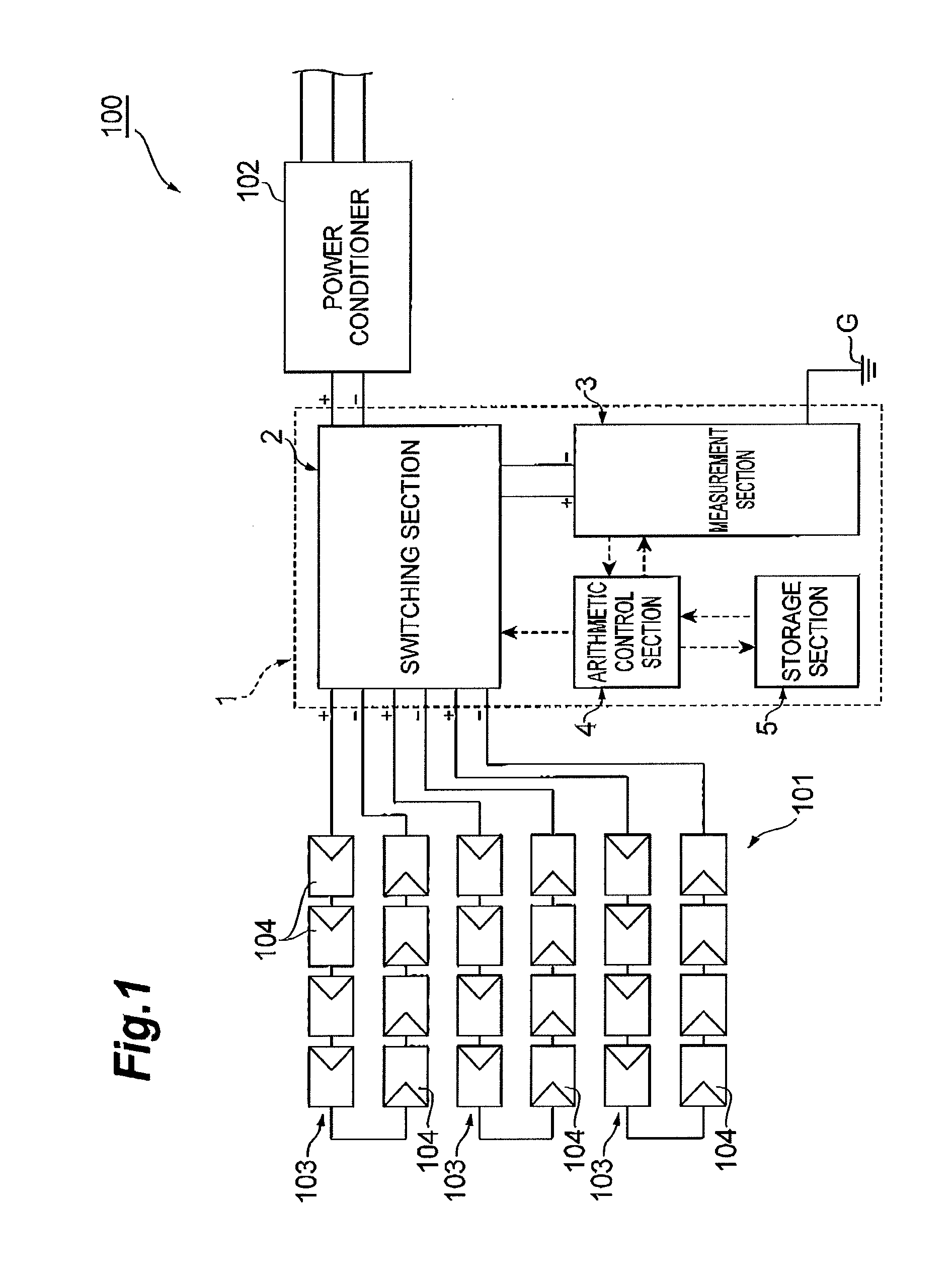
[0049]A first embodiment of the present invention will be described. FIG. 1 is a schematic configuration diagram showing a solar energy generator system including a ground fault detection device according to a first embodiment. As shown in FIG. 1, a ground fault detection device 1 according to the present embodiment is intended to detect a ground fault within a photovoltaic array 101 in a solar energy generator system 100. The solar energy generator system 100 will first be described.
[0050]The solar energy generator system 100 is a generator system for generating electric power using solar energy and includes the photovoltaic array 101 and a power conditioner (load device) 102. The photovoltaic array 101 converts solar energy into electric energy and supplies the electric energy as a DC output to the power conditioner 102. The photovoltaic array 101 includes a plurality of (three here) photovoltaic strings 103 connected in parallel, and each of the plurality of photovoltaic strings ...
second embodiment
[0095]A second embodiment of the present invention will be described. Note that differences from the first embodiment described above will be mainly given in a description of the present embodiment.
[0096]FIG. 6 is a schematic configuration diagram showing a measurement section of a ground fault detection device according to the second embodiment. As shown in FIG. 6, a ground fault detection device 20 according to the present embodiment is different from the ground fault detection device 1 described above in that the ground fault detection device 20 includes a measurement section 23 instead of the measurement section 3 (see FIG. 3).
[0097]The measurement section 23 includes first and second sensing resistors 21 and 22 whose one sides are connected to each other and a current detector 25 which is connected between a junction (connection section) 24 of the first and second sensing resistors 21 and 22 and a ground potential G. The other side (the opposite side from the junction 24) of th...
third embodiment
[0108]A third embodiment of the present invention will be described. Note that differences from the first embodiment described above will be mainly given in a description of the present embodiment.
[0109]FIG. 10 is a schematic configuration diagram showing a switching section of a ground fault detection device according to the third embodiment. FIG. 11 is a schematic configuration diagram showing a measurement section of the ground fault detection device according to the third embodiment. As shown in FIGS. 10 and 11, a ground fault detection device 30 according to the present embodiment is different from the ground fault detection device 1 described above in that the ground fault detection device 30 includes a switching section 32 instead of the switching section 2 (see FIG. 2) and includes a measurement section 33 instead of the measurement section 3 (see FIG. 3).
[0110]As shown in FIG. 10, the switching section 32 includes a switch 37 for measurement. The switch 37 for measurement i...
PUM
 Abstract
Description
Claims
Application Information
 - R&D
- Intellectual Property
- Life Sciences
- Materials
- Tech Scout
- Unparalleled Data Quality
- Higher Quality Content
- 60% Fewer Hallucinations
Browse by: Latest US Patents, China's latest patents, Technical Efficacy Thesaurus, Application Domain, Technology Topic, Popular Technical Reports.
© 2025 PatSnap. All rights reserved.Legal|Privacy policy|Modern Slavery Act Transparency Statement|Sitemap|About US| Contact US: help@patsnap.com


