Optical system for camera

a technology of optical system and camera, applied in the field of optical system for camera, can solve the problems of increasing the difficulty of satisfying optical performance, affecting the relative illumination of the object, and affecting the effect of optical performance, so as to achieve the effect of improving the relative illumination and high resolution

Inactive Publication Date: 2013-10-31
SAMSUNG ELECTRO MECHANICS CO LTD
View PDF12 Cites 76 Cited by
  • Summary
  • Abstract
  • Description
  • Claims
  • Application Information

AI Technical Summary

Benefits of technology

[0013]An object of the present invention is to provide an optical system for a camera capable of implementing a wide angle and a high resolution by sequentially disposing five sheets of lenses having different longitudinal chromatic aberration characteristics and improving an relative illumination (the ratio of corner illumination to the center) by disposing an aperture stop between first and second lenses.

Problems solved by technology

However, when a view angle of a lens is increased, an incident angle of a light ray incident to a lens surface cannot but be increased, such that performance deterioration may be intensified even in the same manufacturing tolerance.
However, it is difficult to satisfy conditions such as miniaturization and cost reduction with an optical system design considering a manufacturing cost of an optical system for a mobile camera.
Therefore, it is difficult to satisfy optical performance and compensate for chromatic aberration with a general optical system design.

Method used


Image

  • Optical system for camera
  • Optical system for camera
  • Optical system for camera

Examples


first exemplary embodiment

[0054]The following Table 1 shows examples of numerical values according to a first exemplary embodiment of the present invention.

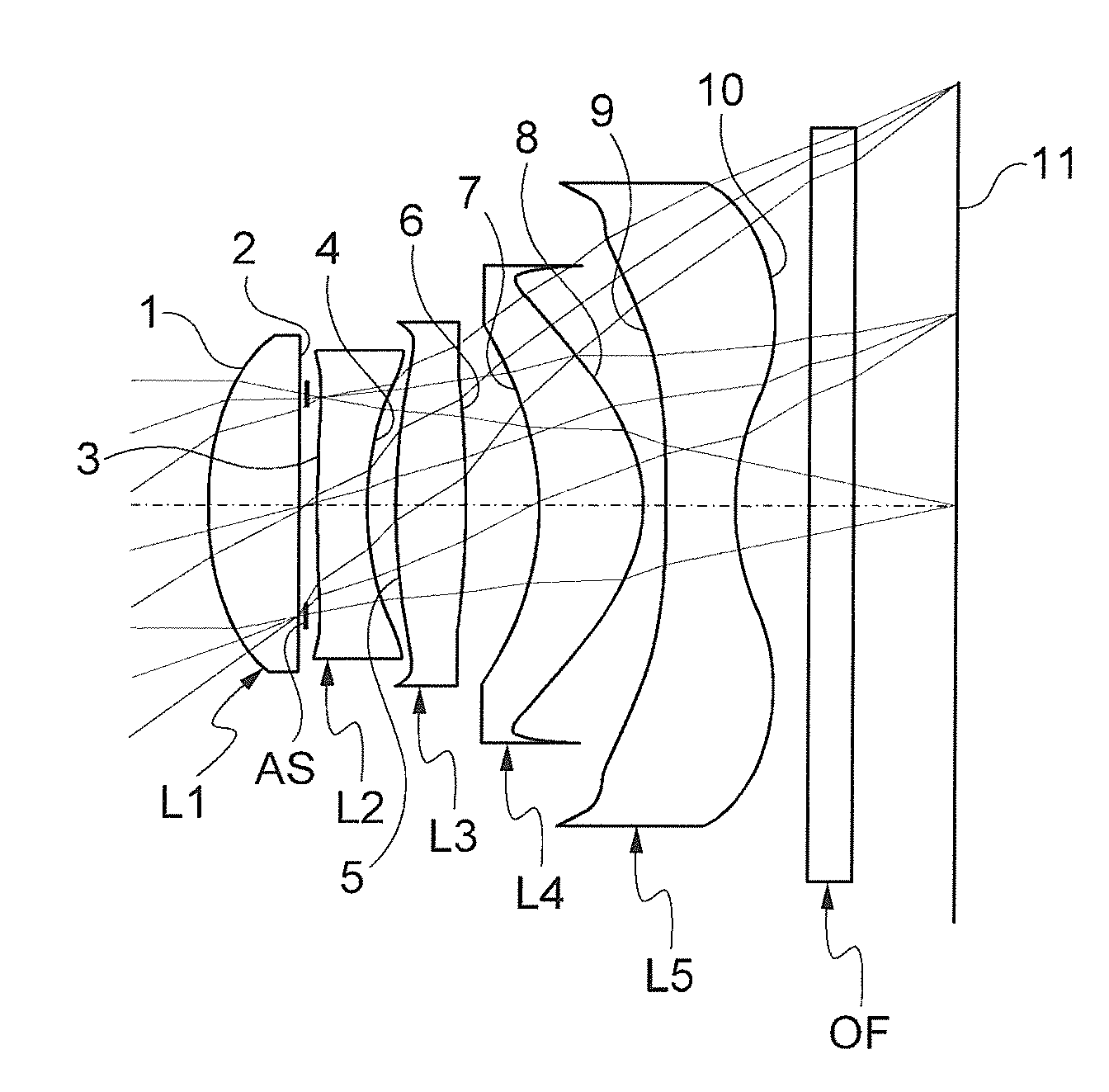
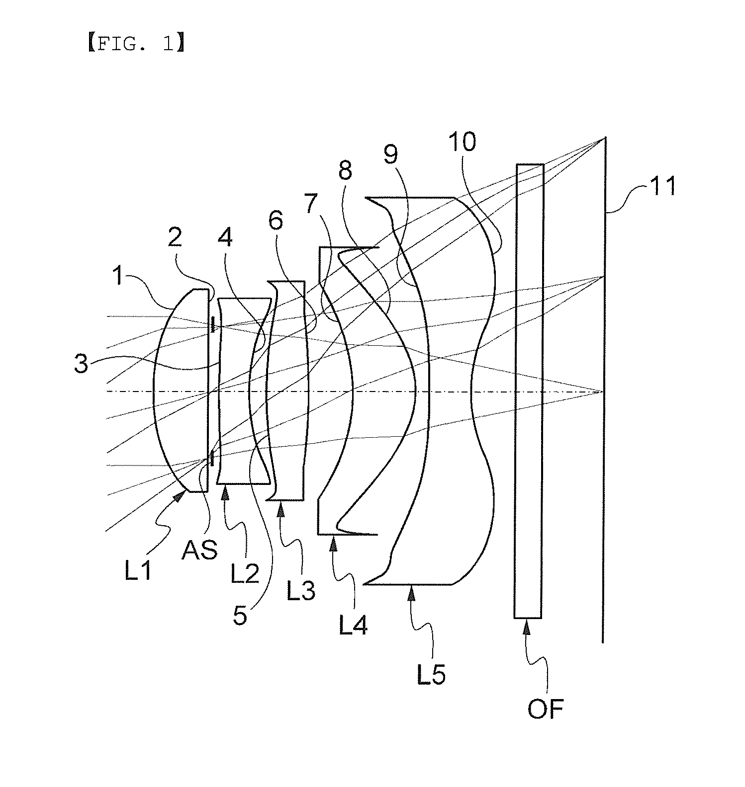
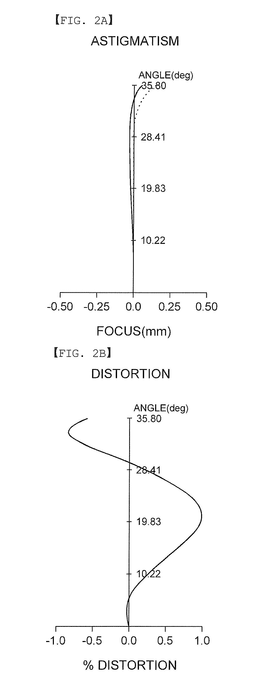
[0055]In addition, FIG. 1 is a lens configuration diagram showing a lens arrangement of an optical system for a camera according to a first exemplary embodiment of the present invention; and FIGS. 2A and 2B are, respectively, views showing astigmatism and distortion of the optical system shown in Table 1 and FIG. 1.

[0056]In the case of the first exemplary embodiment, an effective focal length (f) of the entire optical system is 4.05 mm. In addition, all of the first to fifth lenses L1 to L5 are configured of an aspherical surface plastic lens.

[0057]Further, focal lengths of each lens used in the first exemplary embodiment are as follows: f1=3.66 mm, f2=−3.80 mm, f3=5.09 mm, f4=2.27 mm, and f5=−2.10 mm.

TABLE 1Radius ofSurfaceCurvatureThicknessRefractiveAbbe'sNo.(R)(mm)Power (n)Number (v)Remarks* 11.8480.621.54356.0L1* 223.3790.08* 36.6050.361.63523.7L2* 41...

second exemplary embodiment

[0059]The following Table 3 shows examples of numerical values according to a second exemplary embodiment of the present invention.

[0060]In addition, FIG. 3 is a lens configuration diagram showing a lens arrangement of an optical system for a camera according to a second exemplary embodiment of the present invention; and FIGS. 4A and 4B are, respectively, views showing astigmatism and distortion of the optical system shown in Table 3 and FIG. 3.

[0061]In the case of the second exemplary embodiment, an effective focal length (f) of the entire optical system is 3.94 mm. In addition, all of the first to fifth lenses L1 to L5 are configured of an aspherical surface plastic lens.

[0062]Further, focal lengths of each lens used in the second exemplary embodiment are as follows: f1=3.68 mm, f2=−4.63 mm, f3=5.55 mm, f4=3.80 mm, and f5=−2.51 mm.

TABLE 3Radius ofSurfaceCurvatureThicknessRefractiveAbbe'sNo.(R)(mm)Power (n)Number (v)Remarks* 11.8580.631.54356.0L1* 222.8000.08* 34.0890.321.63523.7L2...

third exemplary embodiment

[0064]The following Table 5 shows examples of numerical values according to a third exemplary embodiment of the present invention.

[0065]In addition, FIG. 5 is a lens configuration diagram showing a lens arrangement of an optical system for a camera according to a third exemplary embodiment of the present invention; and FIGS. 6A and 6B are, respectively, views showing astigmatism and distortion of the optical system shown in Table 5 and FIG. 5.

[0066]In the case of the third exemplary embodiment, an effective focal length (f) of the entire optical system is 4.10 mm. In addition, all of the first to fifth lenses L1 to L5 are configured of an aspherical surface plastic lens.

[0067]Further, focal lengths of each lens used in the third exemplary embodiment are as follows: f1=3.694 mm, f2=−4.620 mm, f3=6.119 mm, f4=2.402 mm, and f5=−2.093 mm.

TABLE 5Radius ofSurfaceCurvatureThicknessRefractiveAbbe'sNo.(R)(mm)Power (n)Number (v)Remarks* 11.7440.601.54356.0L1* 211.3670.03* 310.7290.351.63523.7...


PUM

PropertyMeasurementUnit
view angleaaaaaaaaaa
sizeaaaaaaaaaa

Abstract

Disclosed herein is an optical system for a camera. The optical system for a camera includes: a first lens having positive refractive power and a meniscus shape concave toward an image; a second lens having negative refractive power and a shape concave toward the image; a third lens having the positive refractive power and a shape convex toward an object; a fourth lens having the positive refractive power and a shape convex toward the image; and a fifth lens having the negative refractive power, a shape convex toward the object and concave to the image, and one or more inflection point provided on an image surface.

Description

CROSS REFERENCE(S) TO RELATED APPLICATIONS[0001]This application claims the benefit under 35 U.S.C. Section 119 of Korean Patent Application Serial No. 10-2012-0045609, entitled “Optical System for Camera” filed on Apr. 30, 2012, which is hereby incorporated by reference in its entirety into this application.BACKGROUND OF THE INVENTION[0002]1. Technical Field[0003]The present invention relates to an optical system for a camera, and more particularly, to an optical system for a camera capable of being manufactured in a small size in order to be mounted in a mobile device and implementing a high resolution.[0004]2. Description of the Related Art[0005]Recently, as the use of a mobile communication unit such as a mobile communication terminal, a personal digital assistant (PDA), and a smart phone increases and a service provided through a communication technology is verified, in addition to a basic communication function, various types of additional functions have been mounted. Among th...

Claims


Application Information

Patent Timeline
Patent Type & Authority Applications(United States)
IPC IPC(8): G02B13/00
CPCG02B13/0045G02B1/04G02B9/60G02B13/18
Inventor CHAE, KYU MIN
Owner SAMSUNG ELECTRO MECHANICS CO LTD
Why Eureka
Try Eureka