Electronic control apparatus

a control apparatus and electronic technology, applied in the direction of control/drive circuits, electrical apparatus casings/cabinets/drawers, support structure mounting, etc., can solve the problems of undesirable stress applied to connection terminals and solder parts of printed circuit boards, inability to absorb vibrations in a lateral direction, etc., to increase the number of required parts and increase rigidity

Active Publication Date: 2013-10-31
HITACHI ASTEMO LTD
View PDF8 Cites 24 Cited by
  • Summary
  • Abstract
  • Description
  • Claims
  • Application Information

AI Technical Summary

Benefits of technology

[0004]Therefore, it is an object of the present invention to provide an electronic control apparatus and / or a supporting structure supporting a circuit board designed to support the circuit board reliably even in a lateral direction extending along the surface of the circuit board, or to increase the rigidity in the lateral direction, without increasing the number of required parts.

Problems solved by technology

However, the holding structure disclosed in the above-mentioned Japanese patent document is unable to sufficiently absorb vibrations in a lateral direction substantially parallel to the surfaces of the printed circuit board, transmitted to the printed circuit board from the base member supporting the printed circuit board through the snap fit joint portion.
Therefore, undesirable stress is applied to connection terminals and solder portions of the printed circuit board by the lateral vibrations.

Method used


Image

  • Electronic control apparatus
  • Electronic control apparatus
  • Electronic control apparatus

Examples


Embodiment Construction

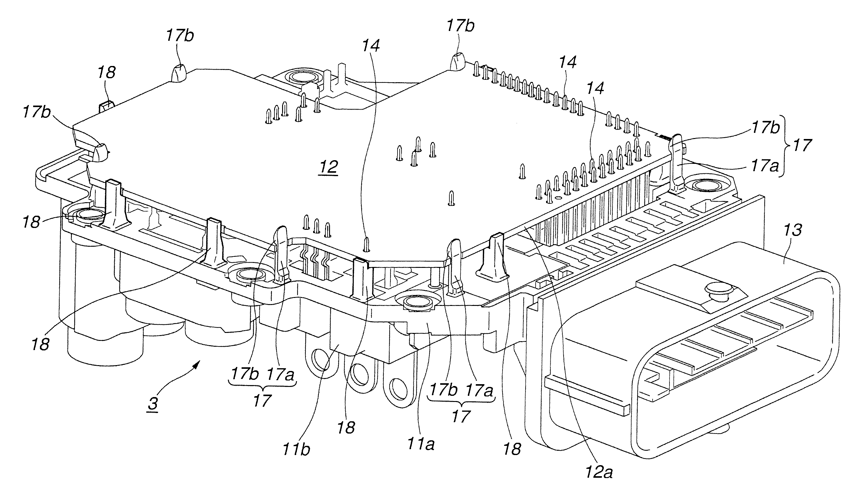
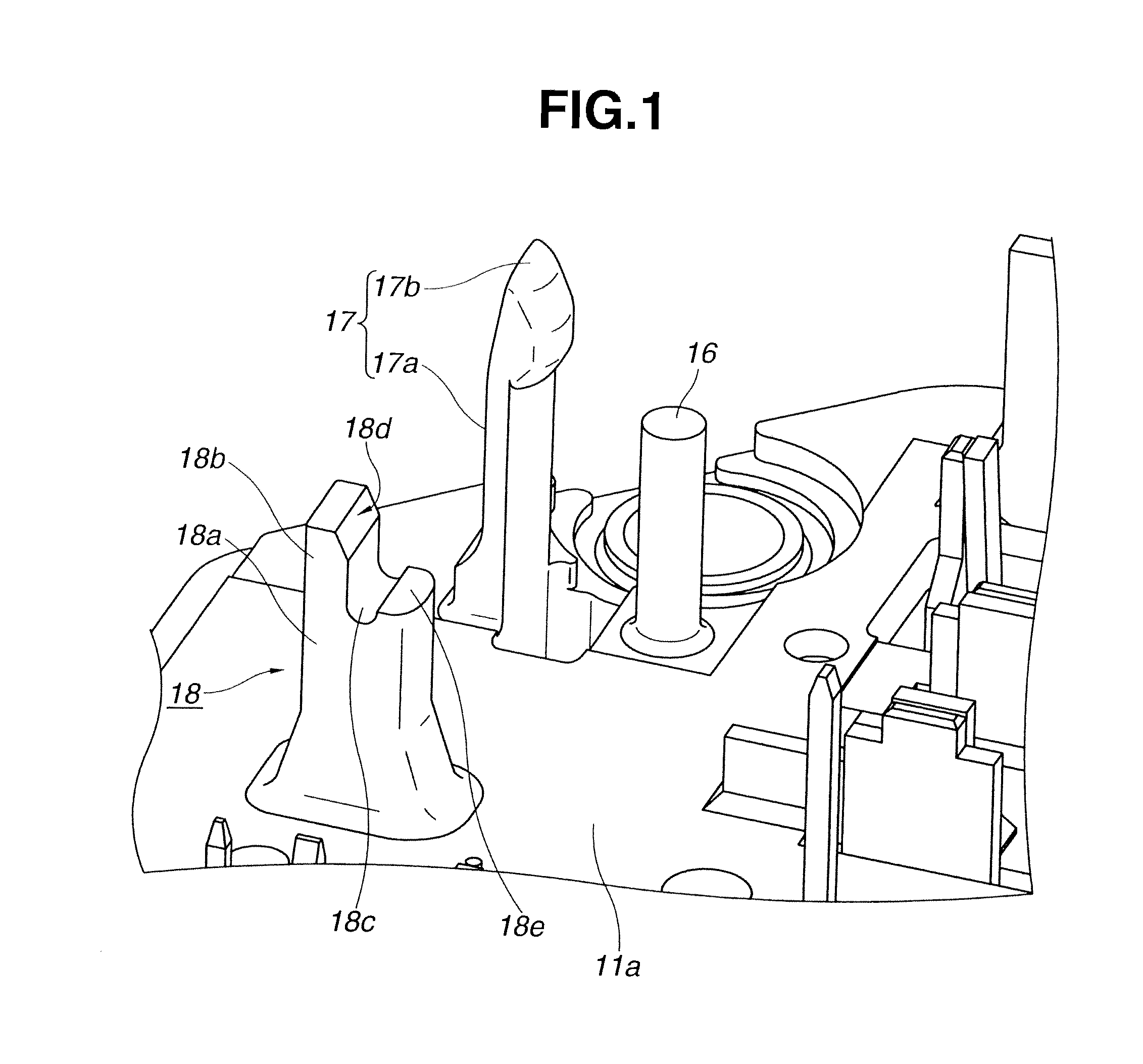
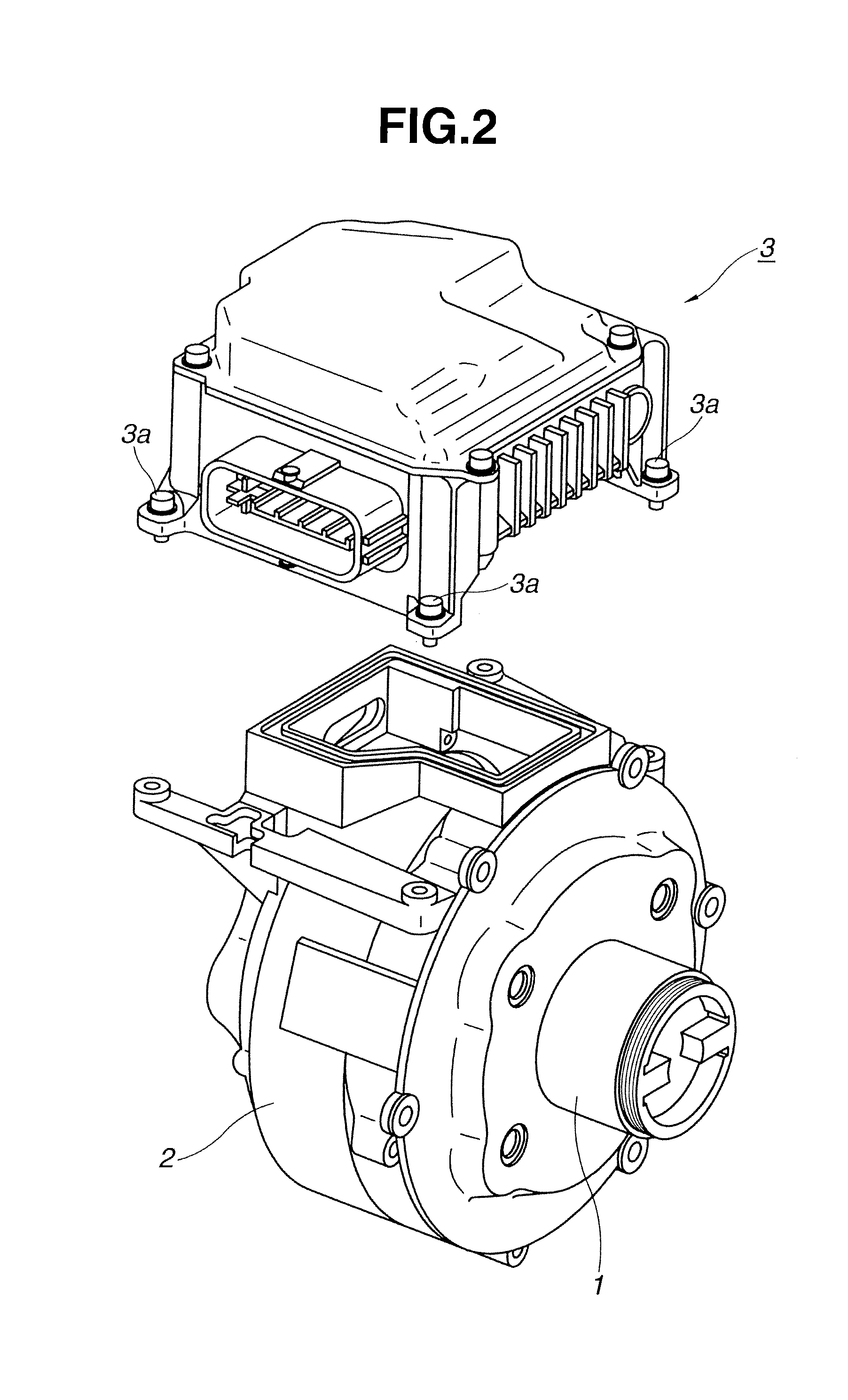
[0013]In an illustrated embodiment, an electronic control apparatus according to the present invention is applied to a brake booster for a motor vehicle.

[0014]In a brake system for a motor vehicle, a brake pedal is connected with a first piston provided in a first cylinder having a smaller cross sectional area, and the first cylinder filled with a hydraulic fluid or oil is connected with a second cylinder having a greater cross sectional area. A second piston provided in the second cylinder is connected with a brake booster. The second cylinder is connected with a wheel brake actuator of each wheel of the vehicle, through an ABS device (anti-lock-brake-system) for preventing tire lock, and / or a VDC device (vehicle dynamics control) for controlling the attitude of the vehicle in case of side slip etc., in this example.

[0015]The hydraulic pressure produced by the depressing force of the brake pedal is increased by the two cylinders, and further increased by the brake booster. The brak...


PUM


Abstract

A supporting structure comprises a base member to support a printed circuit board, a holder standing upright from the base member and supporting the printed circuit board; and a support standing upright from the base member and supporting the printed circuit board sidewise. The support includes a column standing upright from the base member, and having a modulus of elasticity greater than that of the holder, and an abutment portion to abut on a side surface of the printed circuit board.

Description

BACKGROUND OF THE INVENTION[0001]The present invention relates to an electronic control apparatus provided with a printed circuit board or control board and / or a supporting structure of supporting a printed circuit board or control board.[0002]A Japanese patent document JP 2010-62220A shows a supporting structure for a printed circuit board. A printed circuit board (70 as shown in FIG. 2 of this document) is held by a snap fit joint portion which projects downwards from a cover (5) and inserted in a hole of the printed circuit board.SUMMARY OF THE INVENTION[0003]However, the holding structure disclosed in the above-mentioned Japanese patent document is unable to sufficiently absorb vibrations in a lateral direction substantially parallel to the surfaces of the printed circuit board, transmitted to the printed circuit board from the base member supporting the printed circuit board through the snap fit joint portion. Therefore, undesirable stress is applied to connection terminals and...

Claims


Application Information

Patent Timeline
Patent Type & Authority Applications(United States)
IPC IPC(8): H05K7/14
CPCH05K7/1417H02K11/30H02K11/33
Inventor WATANABE, HIROFUMINAKANO, KAZUHIKOYASUKAWA, DAISUKE
Owner HITACHI ASTEMO LTD
Why Eureka
Try Eureka