Quasi-impulsive displacement source

a displacement source and impulsive technology, applied in the field of vibrational seismic sources, can solve the problems of hydraulic systems that are limited in their ability to provide sufficient power, hydraulic fluid is subject to cavitation, and energy is typically not allowed to be intensely released, so as to achieve the effect of imparting energy to the ground

Active Publication Date: 2013-10-31
CONOCOPHILLIPS CO
View PDF17 Cites 5 Cited by
  • Summary
  • Abstract
  • Description
  • Claims
  • Application Information

AI Technical Summary

Benefits of technology

[0008]The invention more particularly relates to a process for delivering a quasi-impulsive impact of band limited spectrum for a seismic prospecting operation wherein an electrically powered seismic source is provided that has a plurality of linear electric motors where a ground contact element of the linear electric motor is provided in proximity with the ground. The ground contact elements of linear electric motors are driven in a coordinated impulse against the ground to deliver a single impulse against the ground and convey seismic energy into the earth that include a broad frequency spectrum for seismically illuminating geophysical structures.
[0009]“Generally vertical” or “generally vertically” should be interpreted as meaning “with an axis of movement sufficiently nearly vertical with respect to the ground so as effectively to impart energy to the ground.” Normally, the axis of movement would be less than 20 degrees to vertical, or in another embodiment less than 10 degrees to vertical.

Problems solved by technology

Explosive charges have long been used as seismic sources although the intense release of energy is typically not permitted except in remote locations.
However, the hydraulic systems are limited in their ability to provide sufficient power at high frequencies due to limitations of hydraulic flow in and out of the hydraulic cylinders.
At very high hydraulic velocities, the hydraulic fluid is subject to cavitation effects when reversing directions that limits the amplitude of the movement of the reaction mass and thus the energy input in to the earth.
At low frequencies, it is difficult for the hydraulic vibe to have enough travel to generate a low frequency wave into the ground.

Method used


Image

  • Quasi-impulsive displacement source
  • Quasi-impulsive displacement source
  • Quasi-impulsive displacement source

Examples


Embodiment Construction

[0014]Turning now to the detailed description of the preferred arrangement or arrangements of the present invention, it should be understood that the inventive features and concepts may be manifested in other arrangements and that the scope of the invention is not limited to the embodiments described or illustrated. The scope of the invention is intended only to be limited by the scope of the claims that follow.

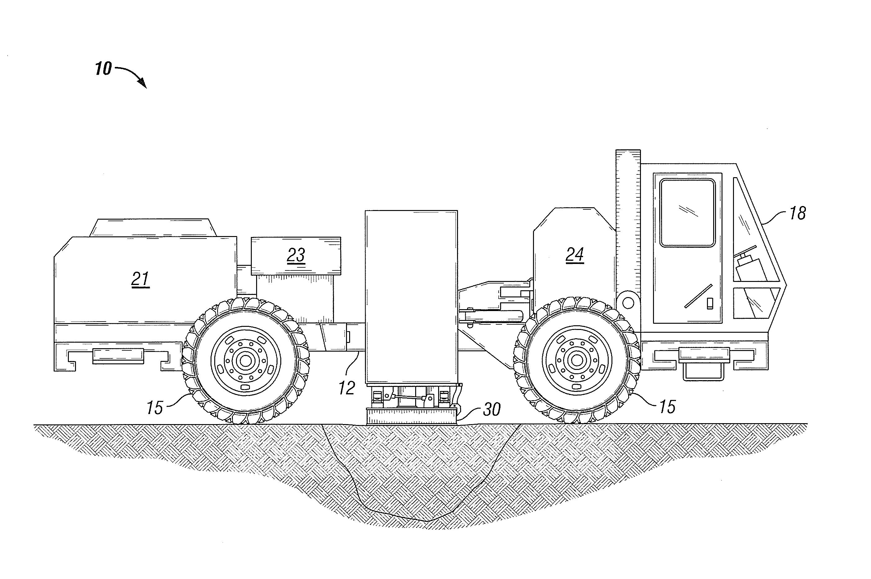
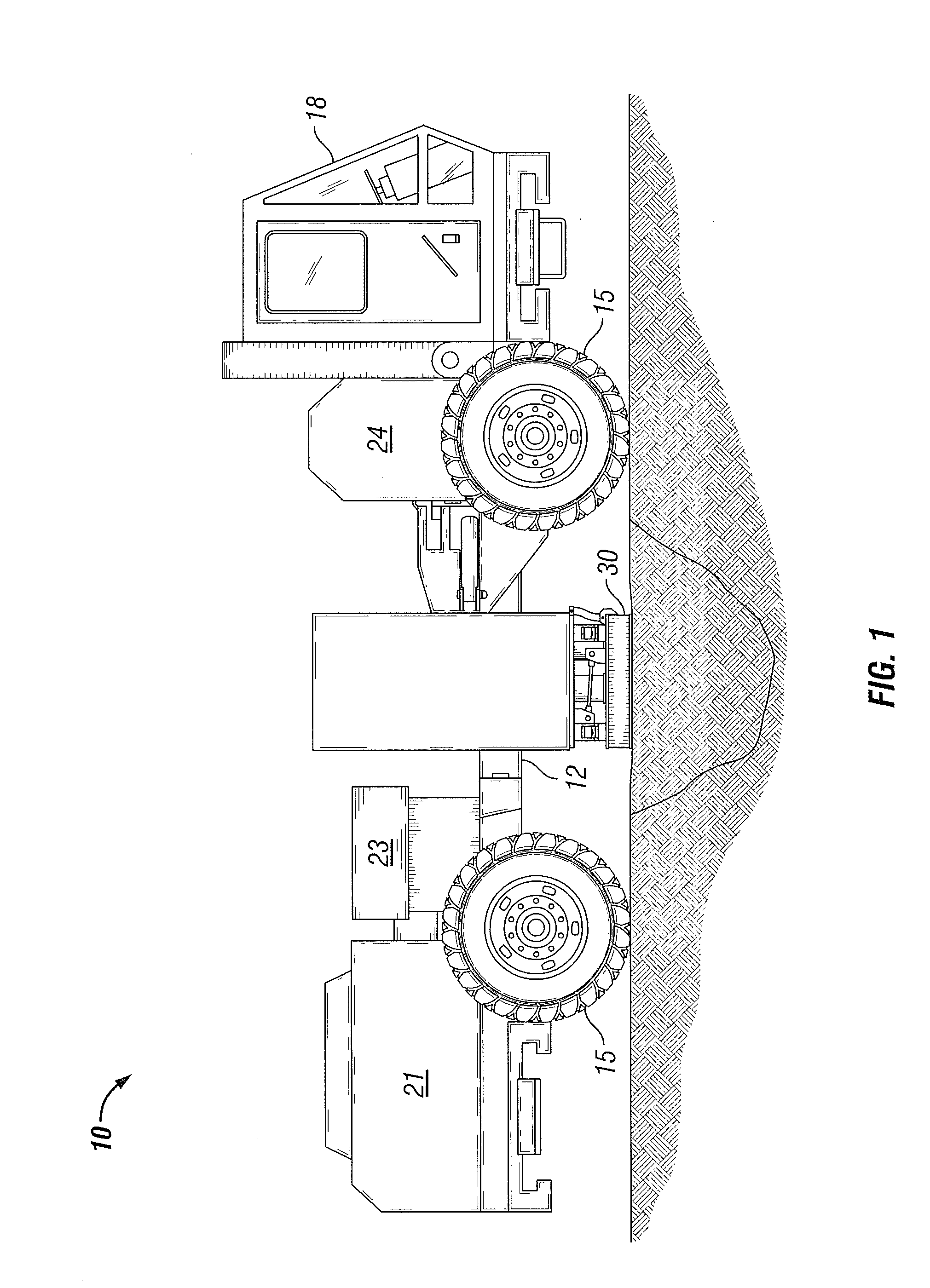
[0015]As shown in FIG. 1, an alternative vibrator actuator source 10 is shown comprising a chassis 12, four wheels 15 and a driver's cab 18. The alternative vibrator actuator source 10 uses a diesel engine 21 to turn an electric generator 23 and uses electric power to power the source 10 both for delivering acoustic energy into the ground and for moving along the ground from location to location. The source 10 utilizes electricity for all of its power needs. A large battery 24 is included to store energy for high situations of high electrical demand or when there are problems...


PUM


Abstract

The invention is an electric seismic vibrator source of the type used in seismic prospecting for hydrocarbons that creates a quasi-impulsive burst of seismic energy onto the ground and into the earth. The source uses an engine and generator combination to create electric power for all systems on the source such as driving a frame of linear electric motors that direct a rod or piston to contact the ground. All of the linear electric motors are driven against the ground in a high power pulse that delivers a band-limited spectrum of seismic energy over a very brief period of time that would like a “pop” and be measured in milliseconds. A quasi-impulsive seismic pulse would create a wave field that resembles the seismic data acquired using dynamite or other explosive seismic systems without the ultrahigh frequencies of a true explosive pulse. The quick burst or several quick bursts may further speed up the survey by minimizing the time that a vibe spends on a source point.

Description

CROSS-REFERENCE TO RELATED APPLICATIONS[0001]This application is a non-provisional application which claims benefit under 35 USC §119(e) to U.S. Provisional Application Ser. No. 61 / 640,411 filed Apr. 30, 2012, entitled “QUASI-IMPULSIVE DISPLACEMENT SOURCE,” which is incorporated herein in its entirety.STATEMENT REGARDING FEDERALLY SPONSORED RESEARCH[0002]None.FIELD OF THE INVENTION[0003]This invention relates to vibratory seismic sources and particularly to seismic sources that are held to the ground to deliver vibratory impulses into the earth for seismic prospecting of hydrocarbons and other subsurface resources.BACKGROUND OF THE INVENTION[0004]In the process of acquiring seismic data, seismic energy is delivered into the earth. Over the years, the preferred attributes of the seismic energy delivered into the earth have been honed to include a broad spectrum of wavelengths and sufficient power across the spectrum to be recorded at the surface. In general, a suitable land source mu...

Claims


Application Information

Patent Timeline
Patent Type & Authority Applications(United States)
IPC IPC(8): G01V1/145G01V1/24
CPCG01V1/145G01V1/24
Inventor EICK, PETER M.BREWER, JOEL D.SHAN, SHAN
Owner CONOCOPHILLIPS CO
Why Eureka
Try Eureka