Continuously variable transmissions and methods therefor

a technology of continuous variable transmission and transmission method, which is applied in the direction of gearing details, mechanical equipment, gearing, etc., can solve the problems that technology has generally been unable to overcome technical and economic hurdles to gain a wider adoption

Inactive Publication Date: 2013-10-31
FALLBROOK INTPROP COMPANY
View PDF0 Cites 72 Cited by
  • Summary
  • Abstract
  • Description
  • Claims
  • Application Information

AI Technical Summary

Problems solved by technology

Although ball-type rolling traction CVTs have gained some acceptance in certain industrial applications, the technology has generally been unable to overcome technical and economic hurdles to gain a wider adoption across multiple fields of use.

Method used


Image

  • Continuously variable transmissions and methods therefor
  • Continuously variable transmissions and methods therefor
  • Continuously variable transmissions and methods therefor

Examples


Embodiment Construction

” one will understand how the features of the system and methods provide several advantages over traditional systems and methods.

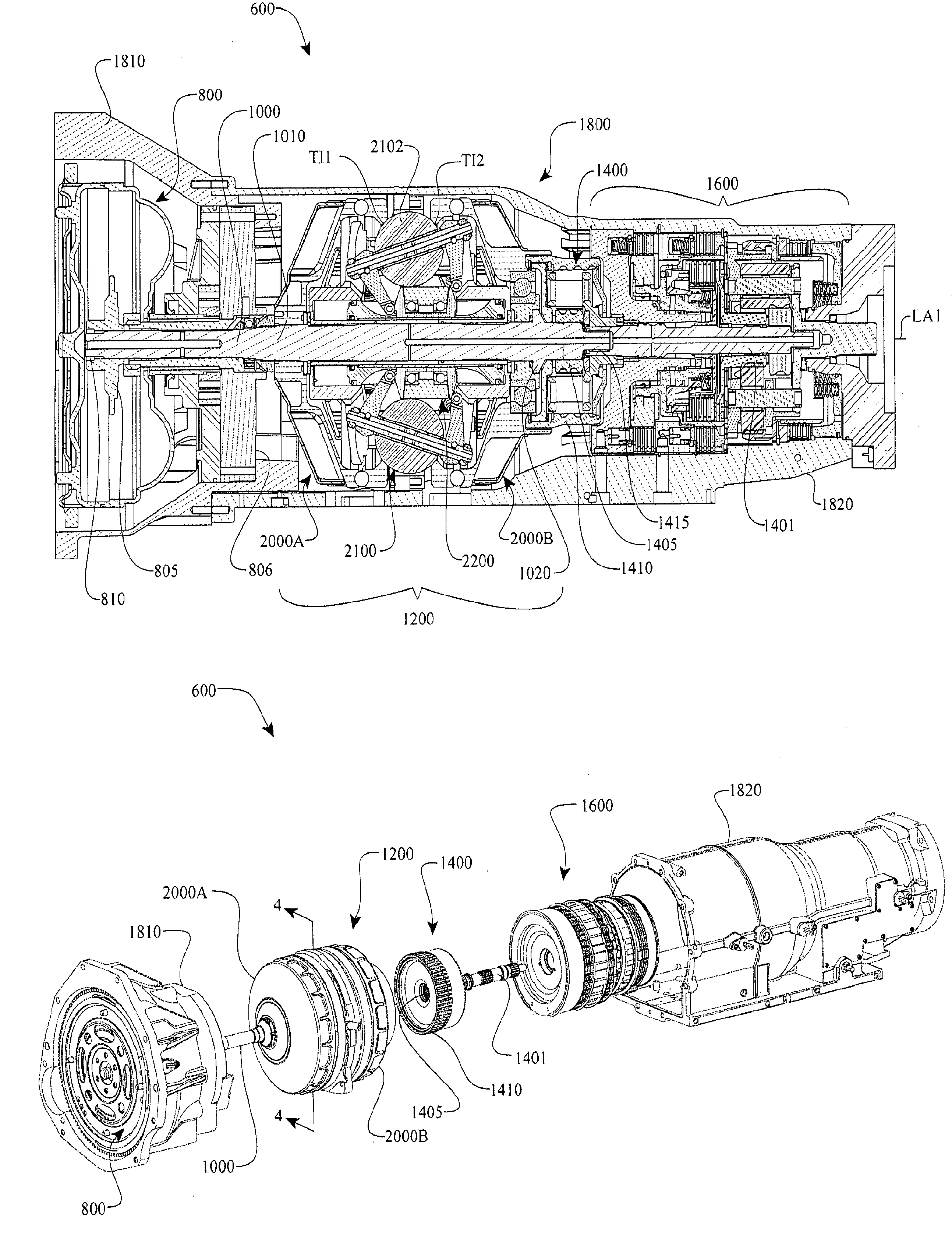
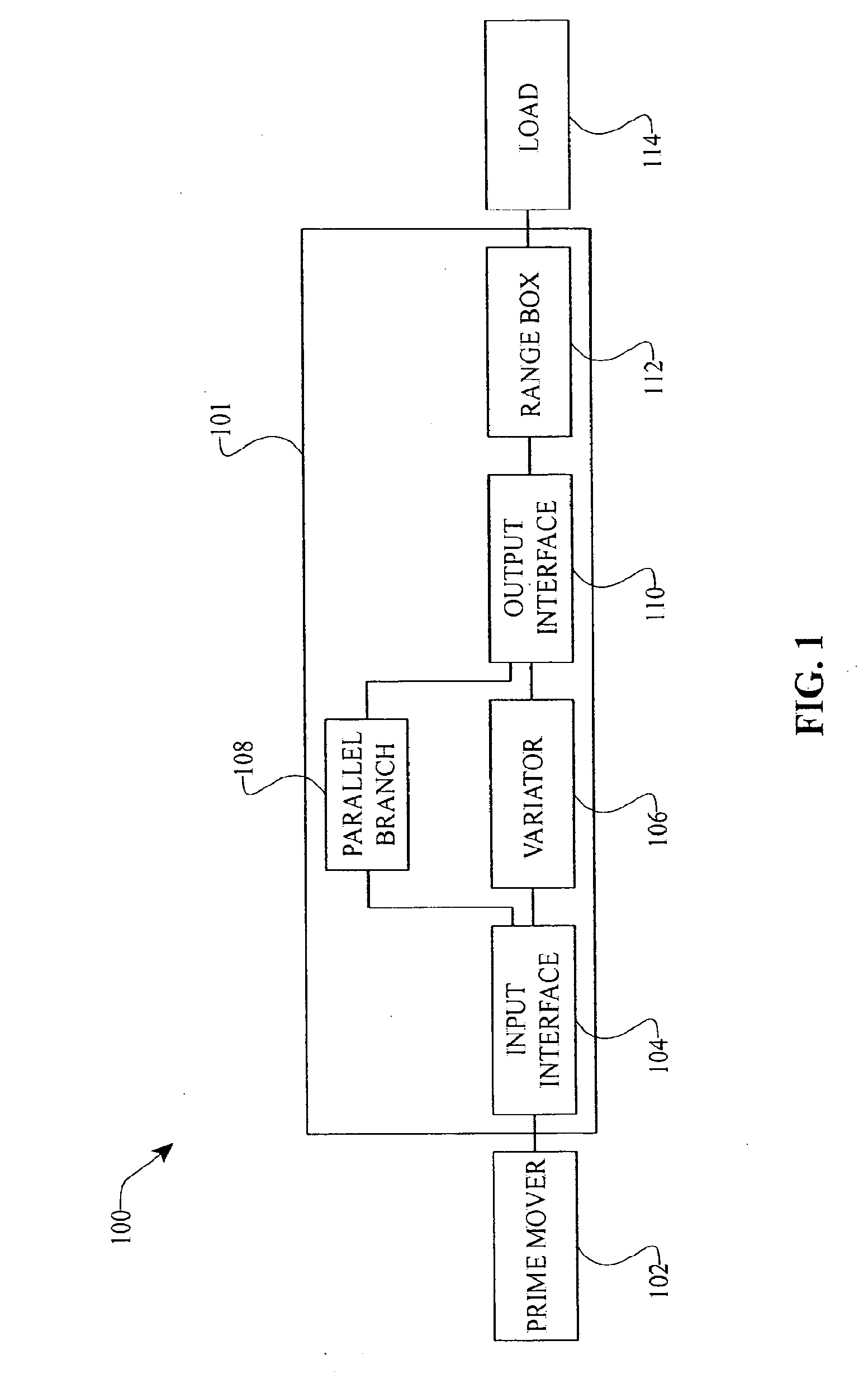
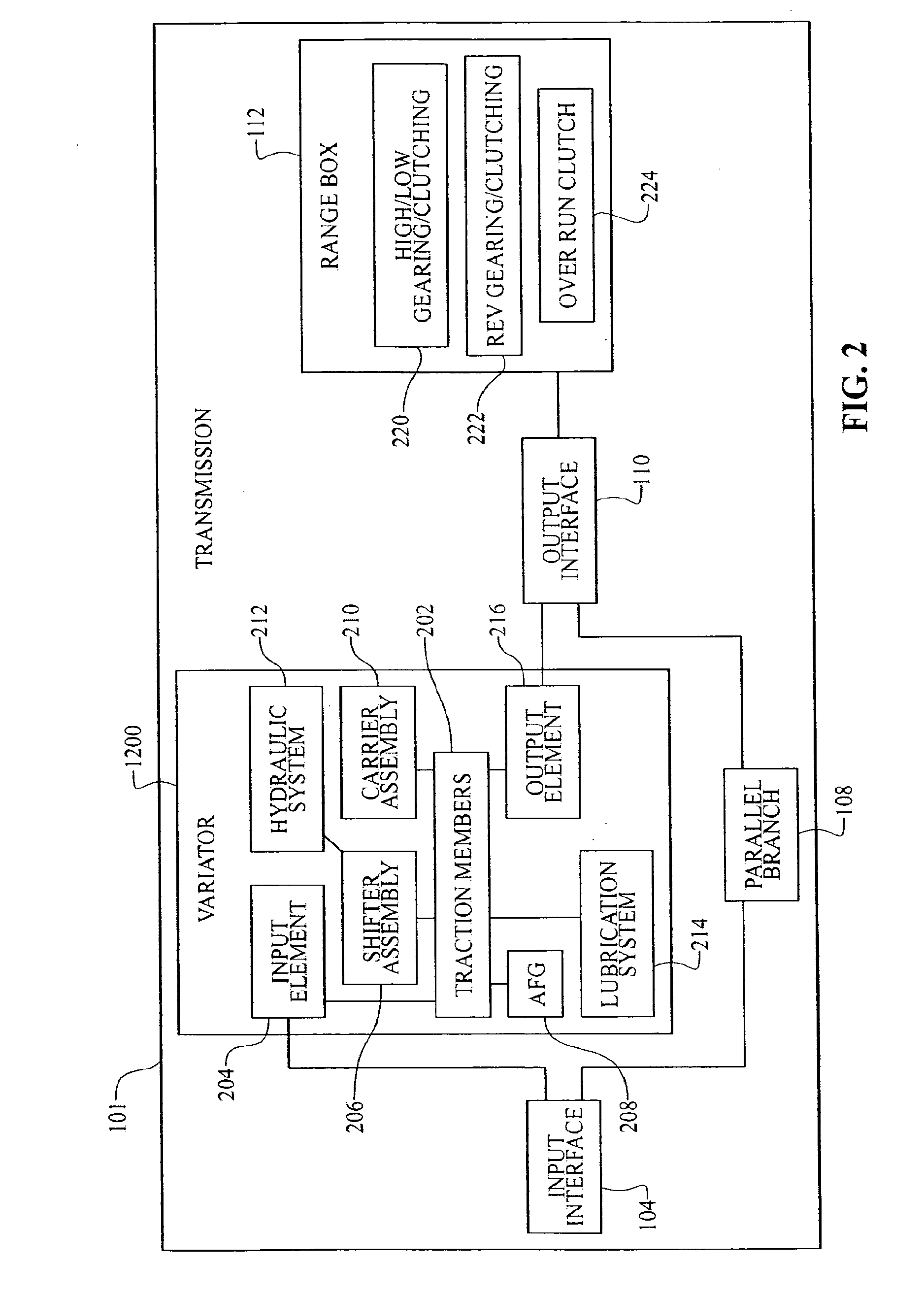
[0008]One aspect of the invention relates to a drive having a prime mover and a transmission coupled to the prime mover. In one embodiment the transmission has a continuously variable unit (CVU), an input interface coupled to the prime mover and to the CVU, and an output interface coupled to the CVU. The drive also has a parallel branch for mechanical power transmission. The parallel branch can be coupled to the input interface and to the output interface.

[0009]Another aspect of the invention addresses a transmission having a main shaft, an input load cam, an input traction ring, and a first set of load cam rollers positioned between the input load cam and the input traction ring. In one embodiment, the transmission has a number of traction planets in contact with the input traction ring, and the transmission has a traction sun in contact with the traction...


PUM


Abstract

Components, subassemblies, systems, and / or methods for continuously variable transmissions (CVT) having a variator provided with a plurality of tilting, traction planets and traction rings are described. In one embodiment, a variator is coupled to a rangebox to provide multiple operating modes. In another embodiment, a hydraulic system is configured to control the transmission ratio of the variator and the rangebox. Shift-cam-and-sun subassemblies can be used to facilitate shifting of the transmission ratio of a CVT. A transmission housing and bell housing can be adapted to house components of a CVT and, in some embodiments, to cooperate with other components of the CVT to support operation and / or functionality of the CVT. Related devices include, for example, a pivot arm, a control feedback mechanism, axial force generation and management mechanisms, a control valve integral with an input shaft, a pivot pin hub, and a rotatable carrier configured to support planet-pivot arm assemblies.

Description

CROSS REFERENCE TO RELATED APPLICATIONS[0001]This application is a continuation of U.S. application Ser. No. 12 / 526,770, filed Aug. 11, 2009, which is a national phase application of Application No. PCT / US2008 / 053347, filed Feb. 7, 2008, which claims the benefit of U.S. Provisional Application No. 60 / 889,512, filed Feb. 12, 2007. The disclosures of all of the above-referenced prior applications, publications, and patents are considered part of the disclosure of this application, and are incorporated by reference herein in their entirety.BACKGROUND OF THE INVENTION[0002]1. Field of the Invention[0003]The disclosed invention relates generally to mechanical power modulation and transmission. More specifically, the invention concerns continuously variable units and transmissions, subassemblies, components, and methods for use therewith.[0004]2. Description of the Related Art[0005]In the relevant technology various types of continuously variable transmissions (CVT) are known. The particu...

Claims


Application Information

Patent Timeline
Patent Type & Authority Applications(United States)
IPC IPC(8): F16H15/50
CPCF16H15/503F16H37/084F16H15/28F16H2037/0886
Inventor CARTER, JEREMYLOHR, CHARLES B.POHL, BRAD P.KIEKE, DAVID
Owner FALLBROOK INTPROP COMPANY
Why Eureka
Try Eureka