Prosthetic device, system and method for increasing vacuum attachment

a technology of prosthetic devices and vacuum attachment, applied in the field of prosthetic devices, can solve the problems of vacuum formation, many known systems have a tendency to lose suction, and the inability to adapt to the volume change of the limb, and achieve the effect of less restriction of the range of motion, rapid and easy releas

Active Publication Date: 2013-10-31
OSSUR HF
View PDF1 Cites 24 Cited by
  • Summary
  • Abstract
  • Description
  • Claims
  • Application Information

AI Technical Summary

Benefits of technology

[0008]Embodiments of the prosthetic device, system and method provide the security and freedom of vacuum suspension without the sensation and restrictions of a sleeve, or the ac...

Problems solved by technology

A significant drawback to known elevated vacuum solutions is they fail to adapt to limb volume change which occurs particularly when a user is walking.
Yet another drawback is that many known systems have a tendency to lose suction due to the method used to seal the socket and hence the vacuum formed.
Many of such vacuum systems are bulky and significantly contribute to the...

Method used


Image

  • Prosthetic device, system and method for increasing vacuum attachment
  • Prosthetic device, system and method for increasing vacuum attachment
  • Prosthetic device, system and method for increasing vacuum attachment

Examples


first embodiment

OF THE PROSTHETIC DEVICE

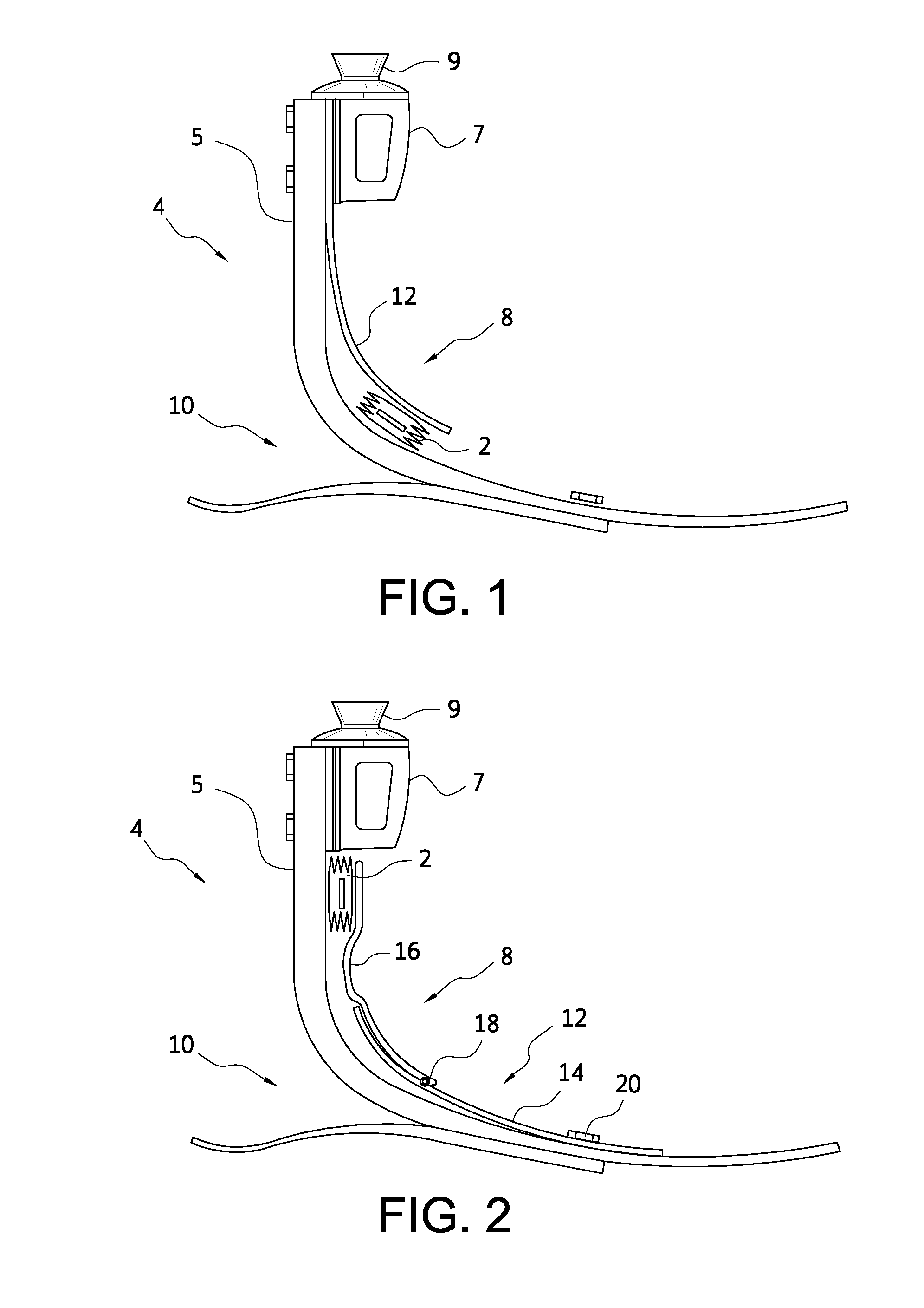
[0070]FIG. 1 shows a first embodiment of the prosthetic device comprising a pump mechanism 2 and a prosthetic foot 4. The pump mechanism 2 has two opposing walls and at least one side wall. The prosthetic foot 4 has an ankle area 8, a heel area 10, and a movable member 12 attached at one end to the prosthetic foot 4 and extending over the front of the prosthetic foot 4 leaving an unattached end. The attached end of the moveable member 12 may be pivoting or non-pivoting. The moveable member 12 generally follows the curvature of the front of the prosthetic foot 4 and a clearance between the moveable member 12 and the front of the prosthetic foot 4 gradually increases. The pump mechanism 2 is placed in the clearance between the movable member 12 and the front of the prosthetic foot 4 within the ankle area 8 near the unattached end of the moveable member 12. One side of the pump is attached to the member 12 and another side of the pump is attached to the prosthet...

second embodiment

OF THE PROSTHETIC DEVICE

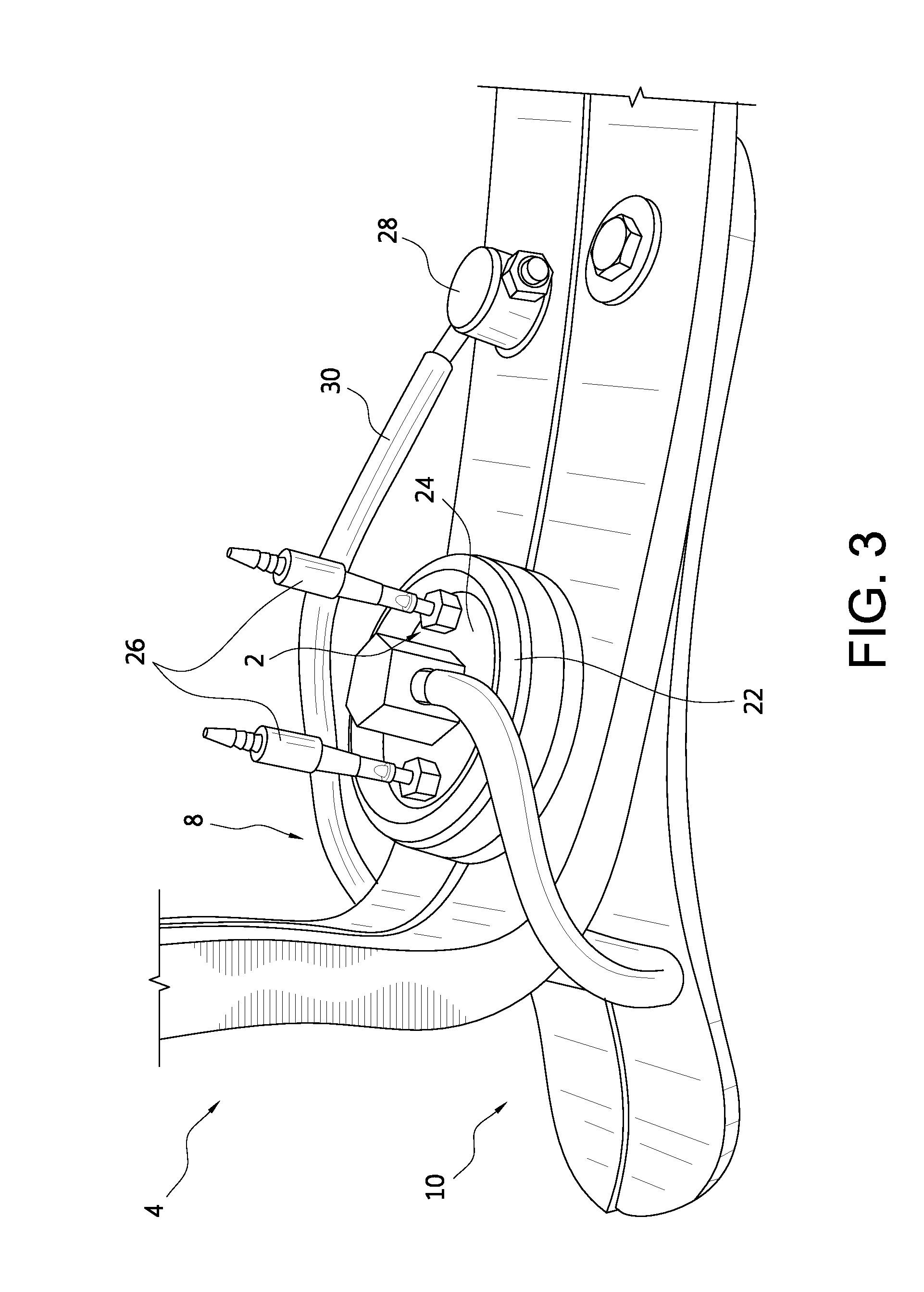
[0076]FIG. 3 shows another embodiment of the prosthetic device comprising a vacuum pump mechanism 2 and a prosthetic foot 4. The vacuum pump mechanism 2 in this embodiment is a membrane-type pump comprising a flexible membrane 22 and a rigid wall 24. The flexible membrane 22 forms a seal with the rigid wall 24. In FIG. 3, this seal may be formed by having the flexible membrane 22 extend over and around the edges of the rigid wall 24 such that the rigid wall 24 fits within a recess formed by the edges of the flexible membrane 22. An airtight seal between the rigid wall 24 and the edges of the flexible membrane 22 may be formed using an adhesive.

[0077]A moveable member 30 is attached at one end to the prosthetic foot 4 in the midfoot area with a pivoting attachment 28, and the moveable member 30 wraps around the heel area 10 of the foot 4. The portion of the moveable member 30 located within the heel area 10 maintains contact with the heel portion of the foot 4...

third embodiment

OF THE PROSTHETIC DEVICE

[0081]FIG. 4 shows another embodiment of the prosthetic device having a prosthetic foot 4 and a membrane-type vacuum pump mechanism 2. The moveable member 30 in this embodiment is formed as a combination of two moveable plates 32, 34. The top plate 32 is connected to the rigid wall 24 and, in FIG. 4, is shown as extending through the rigid wall 24. The bottom plate 34 is connected to the flexible membrane 22 near the membrane's attachment point 40 to the prosthetic foot 4. The bottom plate 34 is also attached to the front of the prosthetic foot 4 in the shin area of the foot 4. The bottom plate 34 follows the curve of the foot 4 by having a substantially constant clearance between the bottom plate 34 and the foot 4. Near the midfoot and forefoot areas, the clearance between the bottom plate 34 and the foot 4 increases so the bottom plate 34 does not impede the gait of the user.

[0082]The top plate 32 is present between the ankle area and the midfoot area of th...


PUM


Abstract

A prosthetic device, system and method is arranged to generate negative pressure inside a prosthetic socket. A pump mechanism is connected to a prosthetic foot and has a fluid chamber in fluid communication with the prosthetic socket during gait for drawing air from the prosthetic socket in step phase, and expelling air into the atmosphere in swing phase. The vacuum assisted suspension results in secure and intimate suspension as the negative pressure formed inside the prosthetic socket holds a residuum firmly to walls of the prosthetic socket. The vacuum is preferably formed at the distal area of the prosthetic socket, and sealed by a suspension liner having a seal component.

Description

FIELD OF ART[0001]The disclosure relates to the field of prosthetic devices, and more particularly to a prosthetic device, system and method for increasing vacuum in a vacuum assisted suspension system.BACKGROUND[0002]With advancements in prosthetic components, improved suspension solutions have become a pressing need. Elevated vacuum suspension has been around for nearly a decade, and improves proprioception and volume control. The concept is well accepted and has gained many users.[0003]Many known elevated vacuum solutions on the market rely solely on sleeves or reflecting liners for placement over a socket to achieve an airtight seal necessary for an effective vacuum. This mode of sealing, particularly sleeves, adds to material thickness over the knee and constrains knee bending dramatically for trans-tibial amputees.[0004]A vacuum in the sense of elevated vacuum solutions refers to creating pressure significantly lower than atmospheric pressure. In prosthetic systems, a vacuum i...

Claims


Application Information

Patent Timeline
IPC IPC(8): A61F2/80
CPCA61F2/80A61F2/68A61F2002/501A61F2002/5067A61F2002/5079A61F2002/607A61F2002/6614A61F2002/6664A61F2002/802A61F2/66A61F2/742A61F2/748A61F2002/805
Inventor HALLDORSSON, OLAFUR FREYRSANDAHL, DAVIDGUNNARSSON, BJARNIEGILSSON, EGILL SVEINBJORN
Owner OSSUR HF
Why Eureka
Try Eureka