
Finger glove for electronics device

a technology of electronic devices and glove fingers, applied in the field of electronic devices, can solve the problems that the capacitive touch screen cannot be operated by the touch of a finger and does not respond to touch, and achieve the effect of economic and efficient, reducing the manufacturing cost of the glov

Inactive Publication Date: 2013-11-07
CHENG RANDY
View PDF10 Cites 16 Cited by
  • Summary
  • Abstract
  • Description
  • Claims
  • Application Information

AI Technical Summary

Benefits of technology

The present invention provides a finger glove that can operate a touch screen device with high precision. The finger glove has a touch receptor at the tip of the finger, which is made of electro-conductive material. The touch receptor has a center high-dense controlling area and a peripheral less-dense regulating area, allowing the wearer to accurately touch the touch screen. The finger glove can be made as a finger sleeve or a glove, and does not require any modifications to its original design. The present invention provides an economic and efficient solution for providing a configuration for the finger glove to operate the touch screen device.

Problems solved by technology

However, the capacitive touch screen can only be operated by the touch of a finger and does not respond to a touch with a conventional stylus, gloves or most other objects.
For example, when a user wears warm keeping gloves or electrical resisting gloves, the screen surface of the capacitive touch screen will not detect a touch of finger through the gloves.

Method used


Image

  • Finger glove for electronics device
  • Finger glove for electronics device
  • Finger glove for electronics device

Examples


first embodiment

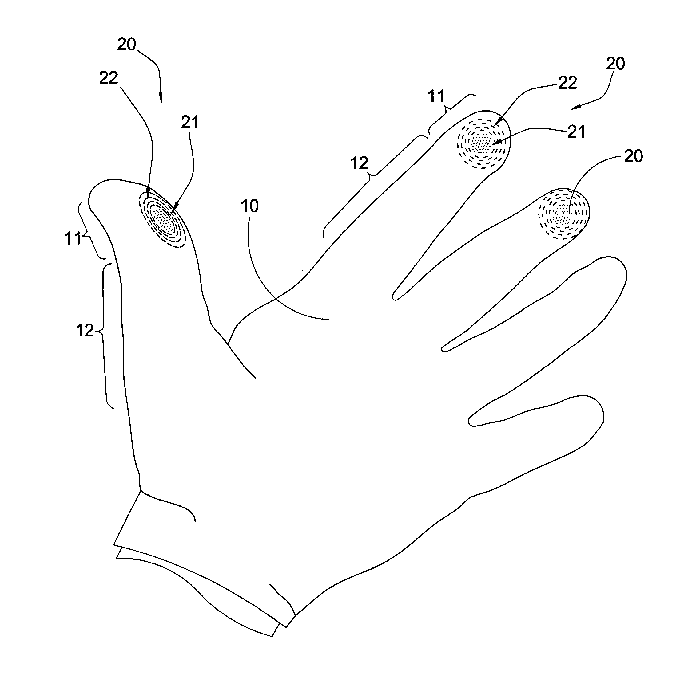
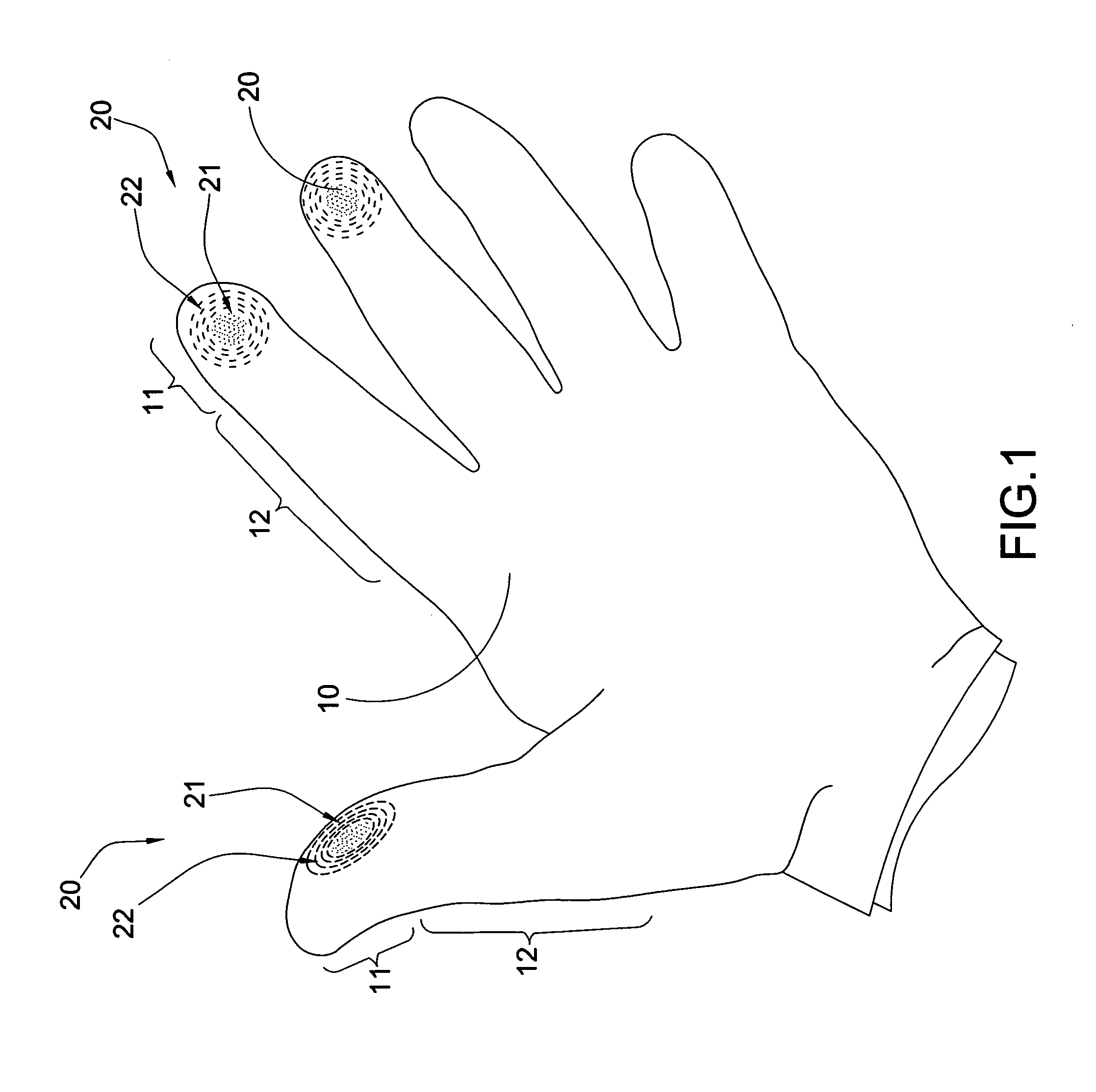
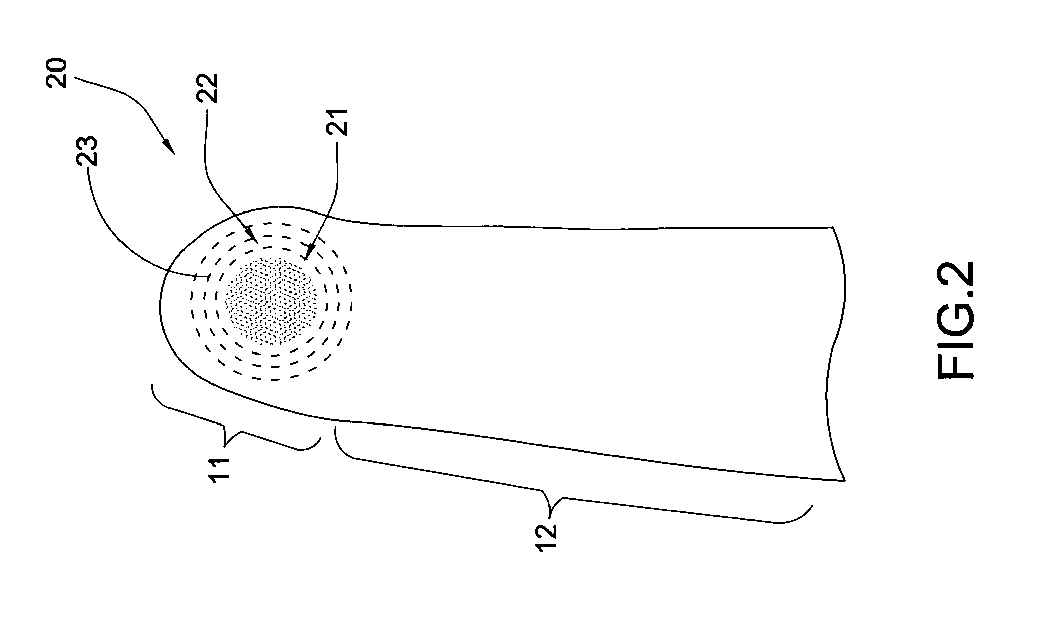
[0021]Referring to FIGS. 1 and 2 of the drawings, a finger glove according to the present invention is illustrated, wherein the finger glove comprises a finger pocket 10 adapted for being worn by a finger of a wearer, and a touch receptor 20 which is made of electro-conductive material.

[0022]According to the first embodiment, the finger glove is embodied as a glove comprising a glove body, which is adapted for being worn by a hand of a user, has a dorsal side, a palm portion, and five finger pockets 10. As shown in FIGS. 1 and 2, each of the finger pockets 10 has a tip portion 11 covering a distal phalanx of the wearer's finger and a finger stall portion 12 extended from the tip portion 11.

[0023]The touch receptor 20 is provided at the tip portion 11 of the finger pocket 10 at an outer surface thereof for responsively contacting with the touch screen of the electronic device, especially the capacitive touch screen.

[0024]According to the first embodiment, the glove body can be made o...

second embodiment

[0033] the finger glove is embodied as a single finger sleeve. As shown in FIGS. 3 and 4, each of the finger pockets 10′ has a tip portion 11′ covering a distal phalanx of the wearer's finger and a finger stall portion 12′ extended from the tip portion 11′. In particular, the finger stall portion 12′ of the glove pocket 10′ is rolled up to form rolled ring and is arranged for being unrolled over the finger of the wearer. Therefore, when the finger glove is worn, the finger of the wearer forms a stylus to operate the touch screen of the electronic device. It is worth mentioning that the wearer is able to wear two or more finger sleeves at different fingers at the same time to operate the touch screen of the electronic device.

[0034]FIGS. 3 and 4 further illustrates the alternative mode of the touch receptor 20′, wherein the touch receptor 20′ is provided at the tip portion 11′ of the finger pocket 10′ at an outer surface thereof for responsively contacting with the touch screen of the...


PUM


Abstract

A finger glove for a touch screen of an electronic device includes a finger pocket adapted for being worn by a finger of a wearer, and a touch receptor which is made of electro-conductive material. The finger pocket has a tip portion covering a distal phalanx of the wearer's finger and a finger stall portion extended from the tip portion. The touch receptor is provided at the tip portion of the finger pocket at an outer surface thereof for responsively contacting with the touch screen of the electronic device.

Description

BACKGROUND OF THE PRESENT INVENTION[0001]1. Field of Invention[0002]The present invention relates to an electronic device with touch screen configuration, and more particular to a finger glove for the electronic device, wherein the wearer is able to wear the glove to operate the touch screen device.[0003]2. Description of Related Arts[0004]Touch-screen input becomes a mainstream for electronic devices, such as mobile phone and personal computer. In fact, most portable electronic devices, such as “Apple iPhone or iPad” are only operated by the virtual keyboard without any physical QWERTY keyboard. In other words, the users can only use their fingers to operate the electronic devices. Generally speaking, the capacitive touch screen requires bare-handed finger contact to touch on the screen surface. Unlike the conventional resistive screen, the capacitive touch screen does not rely on pressure on the screen surface, such that the capacitive touch screen is more responsive than the resi...

Claims


Application Information

Patent Timeline
Patent Type & Authority Applications(United States)
IPC IPC(8): A41D19/00
CPCG06F3/014
Inventor CHENG, RANDY
Owner CHENG RANDY
Learn More