Self-inking marking device

a marking device and self-inking technology, applied in the field of marking devices, can solve the problems of increasing the difficulty of adjustment, difficult and tedious, and the prior art's marking devices suffer from a myriad of problems, so as to prevent inadvertent access, protect the user from the risk of getting ink on his fingers, clothes, or other surrounding materials, and easily change the ink source

Active Publication Date: 2013-11-07
NAVITOR
View PDF5 Cites 22 Cited by
  • Summary
  • Abstract
  • Description
  • Claims
  • Application Information

AI Technical Summary

Benefits of technology

[0025]In an embodiment, a retracting sheath encloses the rolling ink cartridge. In an embodiment, the protective sheath provides a protective shield over a portion of the ink cartridge, including but not limited to 40%-60% of the ink cartridge, that is exposed to the user at the bottom of the marking device. In an embodiment, when the marking device is in a neutral, non-printing position, the sheath closes and seals off the cartridge to prevent inadvertent access. In another embodiment, when the marking device is in a roller-changing position having a swingarm actuated outward, the sheath is in a closed position. Subsequently, when the roller is snapped into place within the swingarm, the motion of the placement or snapping into place opens the sheath. In operation, when the ink cartridge is moved via a swingarm to affect inking, the sheath is moved underneath the protective shield portion to allow inking of the die plate. Therefore, in another feature and advantage of embodiments of the invention, the user is protected from the risk of getting ink on his fingers, clothes, or other surrounding materials by the retracting sheath.
[0026]In an embodiment, a locking mechanism is provided that allows access to the ink roller or ink source in order to more easily change the ink source. In an embodiment, the locking mechanism secures the upper body in a depressed position such that the swingarm is actuated outward as it would be during inking and stamping. In another embodiment, the locking mechanism secures the swingarm itself when it is manually actuated outward by the user so that the upper body can remain in its extended neutral position.
[0027]In another embodiment of the invention, a die plate is pivotably mounted to a central support structure or date housing of the marking device. The die plate is mounted such that it pivots about a single pivot axis as the swing arm and ink roller pass over the die plate and print band(s) during a single actuation or stroke of the self-marking device. This allows for sufficient clearance of the swing arm from the die plate even after multiple uses so that smooth and easy actuation of the device is not inhibited.
[0028]In yet another embodiment of the invention, the ink roller assembly includes a swing arm similar to other embodiments and pivotably mounted on a lower housing of the self-marking device, an ink roller rotatably carried on the swing arm, and bearings on each end of the ink roller. An outer circumference of each bearing is configured to roll along a hard surface of the die plate so as to maintain the ink roller at a fixed distance from the die place creating a fixed amount of compression for the ink roller. Over-inking of the die plate and / or print band(s) is thereby reduced or avoided altogether.

Problems solved by technology

However, marking devices of the prior art suffer from a myriad of problems, especially in the context of marking devices incorporating adjustable daters or other adjustable print heads.
This is often difficult and tedious, as the wheels are generally smaller than is comfortable to the interface of the average human finger.
These wheels can often be located within a recessed housing, thus increasing the difficulty of adjustment.
These wheels are often placed close together, further complicating the band adjustment process.
The user experience in daters of the prior art is further worsened by the lack of visibility into what is currently set at the print interface.
As a result, the user is often required to resort to trial and error or a recursive process of adjusting a wheel and examining the print interface in order to see which bands are being adjusted to what setting.
Clearly, the above described processes of inverting the dater in order to view the print interface and / or partially or fully projecting the die plate from the ink source on self-inking daters of the prior art, often while trying to adjust the print bands, combined with the forced backwards reading of the print interface are wildly inefficient.
However, activating this locking feature necessarily requires an extra step when adjusting the print interface.
In addition, because the user must closely examine or inspect the print interface on traditional daters in order to learn of the current position of the print bands, the risk of the user inadvertently getting ink on his fingers, clothes, or other surrounding materials is greatly increased.
This problem is exacerbated in self-inking daters of the prior art where the user must press on the handle with one hand and stabilize the body with the other hand in order to rotate the die plate from the ink source (and near the user's stabilizing hand at the printing end), or activate a locking feature that keeps the die plate in the projected position.
This problem is further exacerbated in daters of the prior art where adjustment wheels are located within a recessed body near the ink source.
Numberers of the prior art typically suffer from the same problems as described above with respect to daters.

Method used


Image

  • Self-inking marking device
  • Self-inking marking device
  • Self-inking marking device

Examples


Embodiment Construction

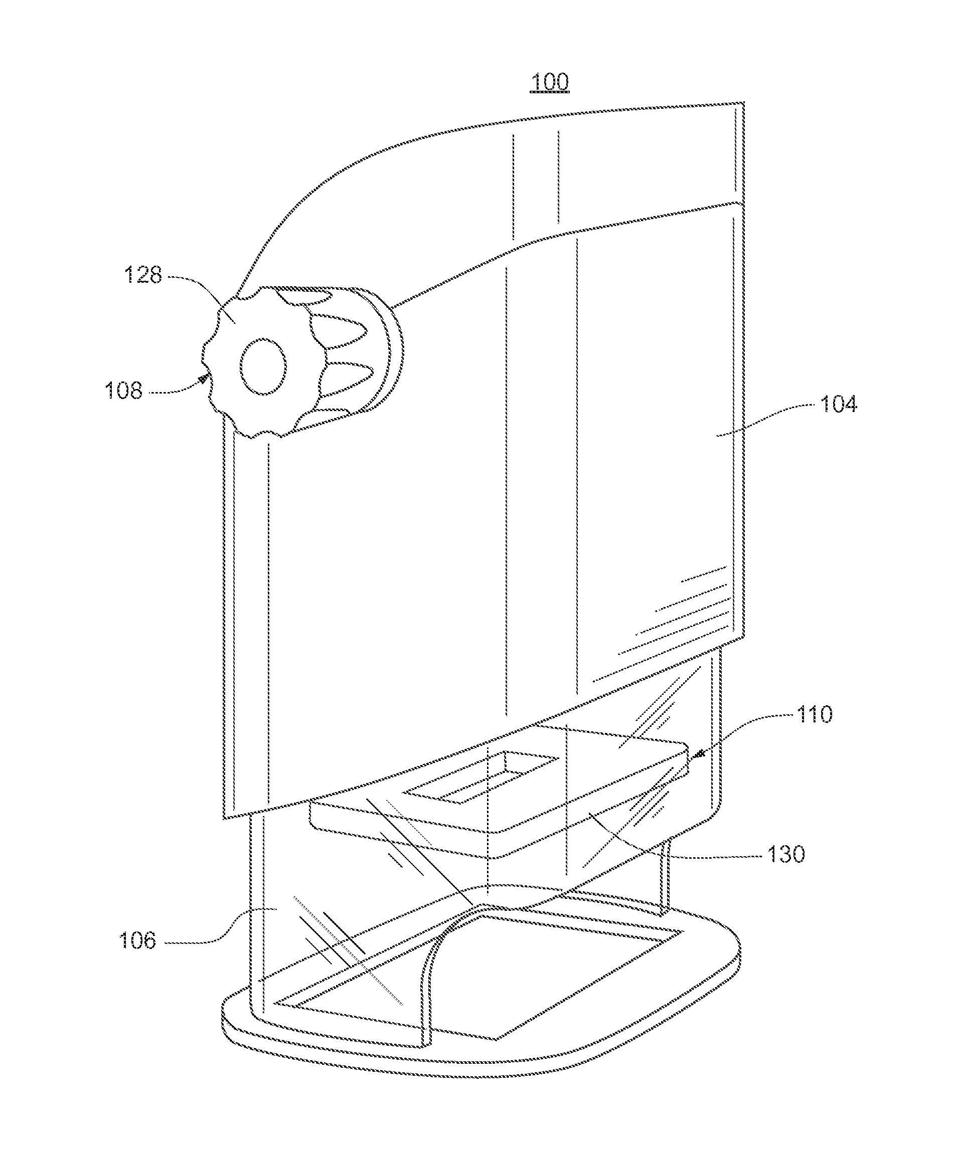
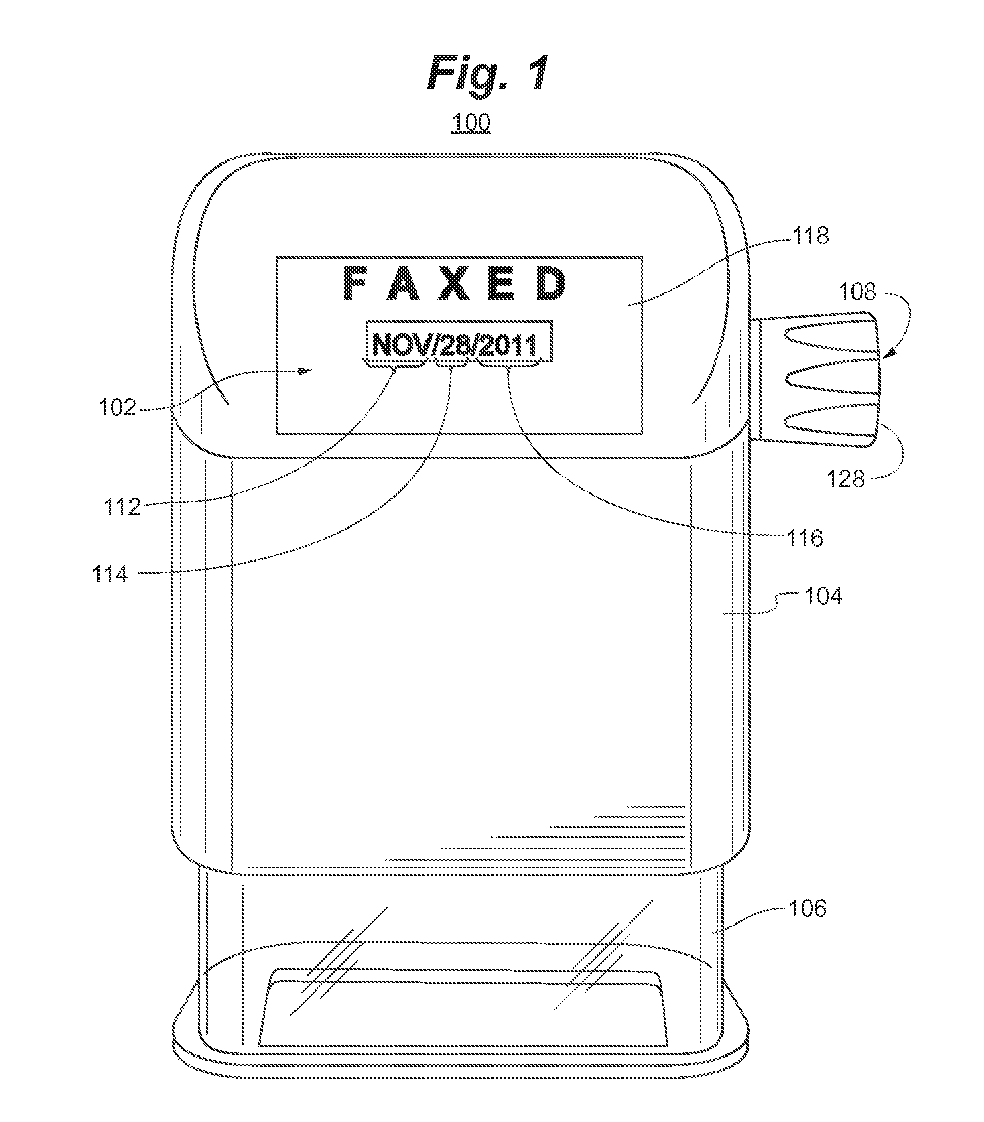
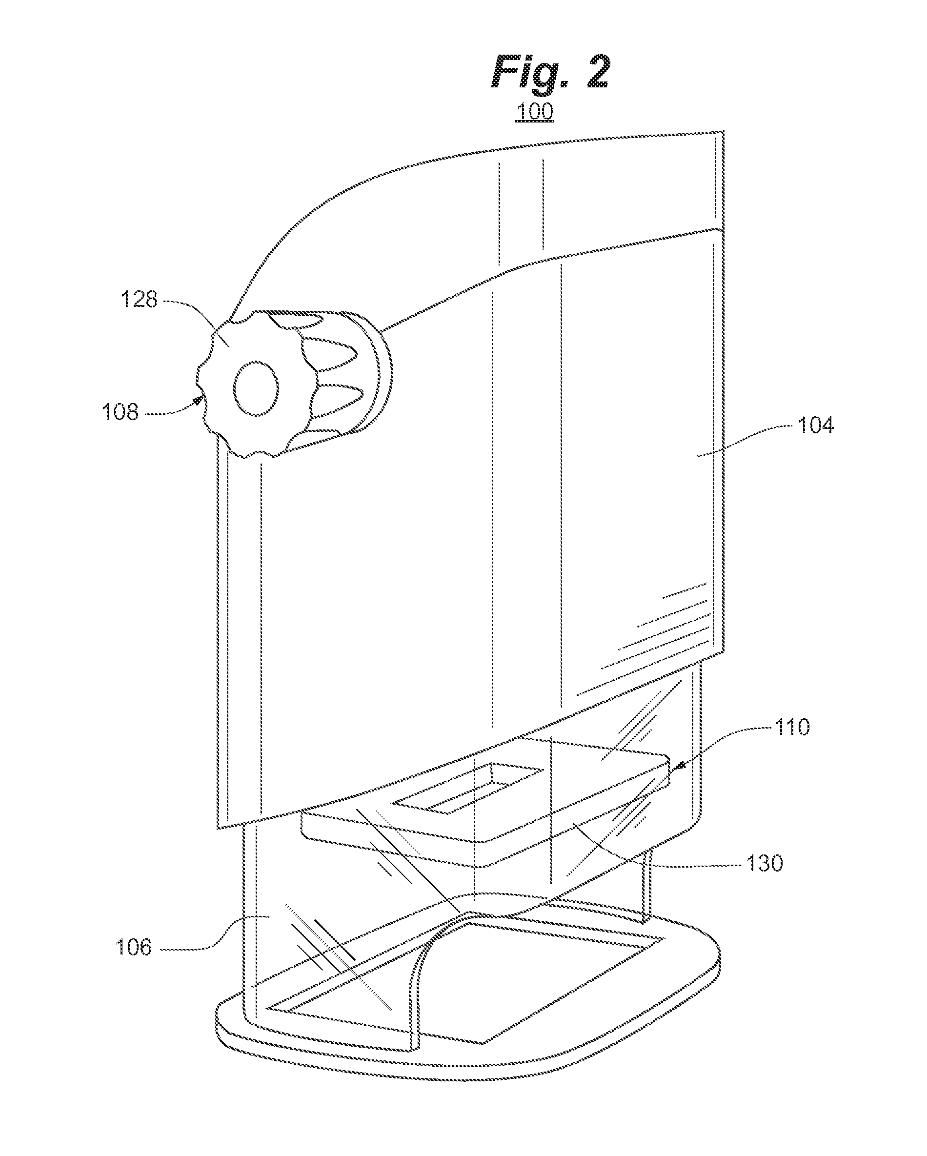
[0063]Referring generally to FIGS. 1-5, a self-inking marking or stamping device 100 according to an embodiment is depicted. Marking device 100 generally includes display interface 102, upper body 104, lower body 106, adjustment components 108, and printing components 110.

[0064]Display interface 102 comprises a month display 112, day display 114, year display 116, and optionally, a fixed or interchangeable display card 118. Month display 112 reflects the month value of the print band of months that is currently in the printing position. For example, in the embodiment depicted by FIGS. 1-5, month display 112 is “NOV” for November. Similarly, day display 114 reflects the day value of the print band(s) of days that is currently in the printing position. For example, in the embodiment depicted by FIGS. 1-5, day display 114 is “28,” reflecting the 28th day of the month. Likewise, year display 116 reflects the year value of the print band(s) of years that is currently in the printing posi...


PUM


Abstract

A self-inking marking device having adjustable print bands configured to be adjustable by a single adjustment knob, with a readily viewable display for viewing the current status of the print interface. In an embodiment, a self-inking marking device generally includes a display interface, an upper body, a lower body, adjustment components, and printing components. The printing components include components to affect a unique self-inking method that utilizes an ink roller that inks the die while rolling along the surface of the die plate.

Description

RELATED APPLICATION[0001]The present application claims the benefit of U.S. Provisional Application No. 61 / 590,415, filed Jan. 25, 2012, and also claims benefit to U.S. Provisional Application No. 61 / 715,652, filed Oct. 18, 2012, both which are incorporated herein in their entirety by reference.TECHNICAL FIELD[0002]The invention relates generally to marking devices, including, for example, hand stamps, and more particularly, to self-inking marking devices with adjustable print bands.BACKGROUND[0003]Marking devices that imprint information from a die onto a sheet of paper or other receiving surface have been used in the art for some time. Marking devices of the prior art, for example, traditional hand stamps, originally required a user to depress the die into an ink source, where ink would be deposited onto the die, and subsequently required the user to depress the inked die onto the receiving surface. More recently, self-inking stamps utilizing a spring force and an internally-incor...

Claims


Application Information

Patent Timeline
Patent Type & Authority Applications(United States)
IPC IPC(8): B41K1/10
CPCB41K1/10B41K1/12B41K1/42
Inventor ANTHONY, JOHNWILLIAMS, RICHORRICO, JAMES
Owner NAVITOR
Why Eureka
Try Eureka