
Installation structure of countertop faucet

a countertop faucet and installation structure technology, applied in the direction of mechanical equipment, engine components, transportation and packaging, etc., can solve the problems of saving a great amount of installation time and a lot of installation troubles, and achieve efficient installation of the faucet, efficient disassembly and removal of the faucet, and efficient fitting into the receiving bore

Inactive Publication Date: 2013-11-07
CHEN MING HUNG +1
View PDF8 Cites 13 Cited by
  • Summary
  • Abstract
  • Description
  • Claims
  • Application Information

AI Technical Summary

Benefits of technology

The present invention provides an installation structure of a countertop faucet that enables easy, efficient, and simple mounting / dismounting of the faucet on a counter, such as a lavatory counter and a basin counter. The locking nut secures the base to the counter to allow the joint section of the faucet to efficiently fit into the receiving bore of the base. The positioning modules of the faucet allow for efficient installation by achieving retaining engagement with the positioning holes of the two positioning modules. The push buttons of the faucet allow for efficient dismounting and removal of the faucet by pushaway of the positioning beads that are in engagement with the positioning holes. The arrangement of two stop valves prevents leakage of water during installation, saving time and installation troubles. The receiving bore has inner surface with slide grooves that guide the positioning beads so that the faucet is only allowed to be jointed to the base at a predetermined direction, preventing incorrect installation. The technical effects of the invention include easy and efficient installation of countertop faucets with reduced installation time and troubles.

Problems solved by technology

This saves a great amount of installation time and also saves a lot of troubles of installation.

Method used


Image

  • Installation structure of countertop faucet
  • Installation structure of countertop faucet
  • Installation structure of countertop faucet

Examples


Embodiment Construction

[0019]The following descriptions are exemplary embodiments only, and are not intended to limit the scope, applicability or configuration of the invention in any way. Rather, the following description provides a convenient illustration for implementing exemplary embodiments of the invention. Various changes to the described embodiments may be made in the function and arrangement of the elements described without departing from the scope of the invention as set forth in the appended claims.

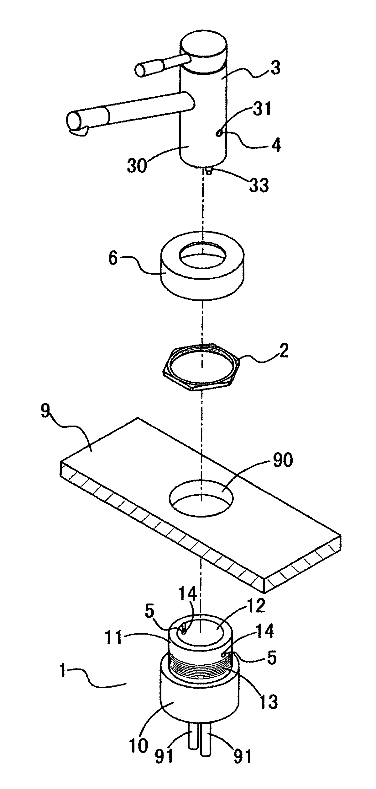
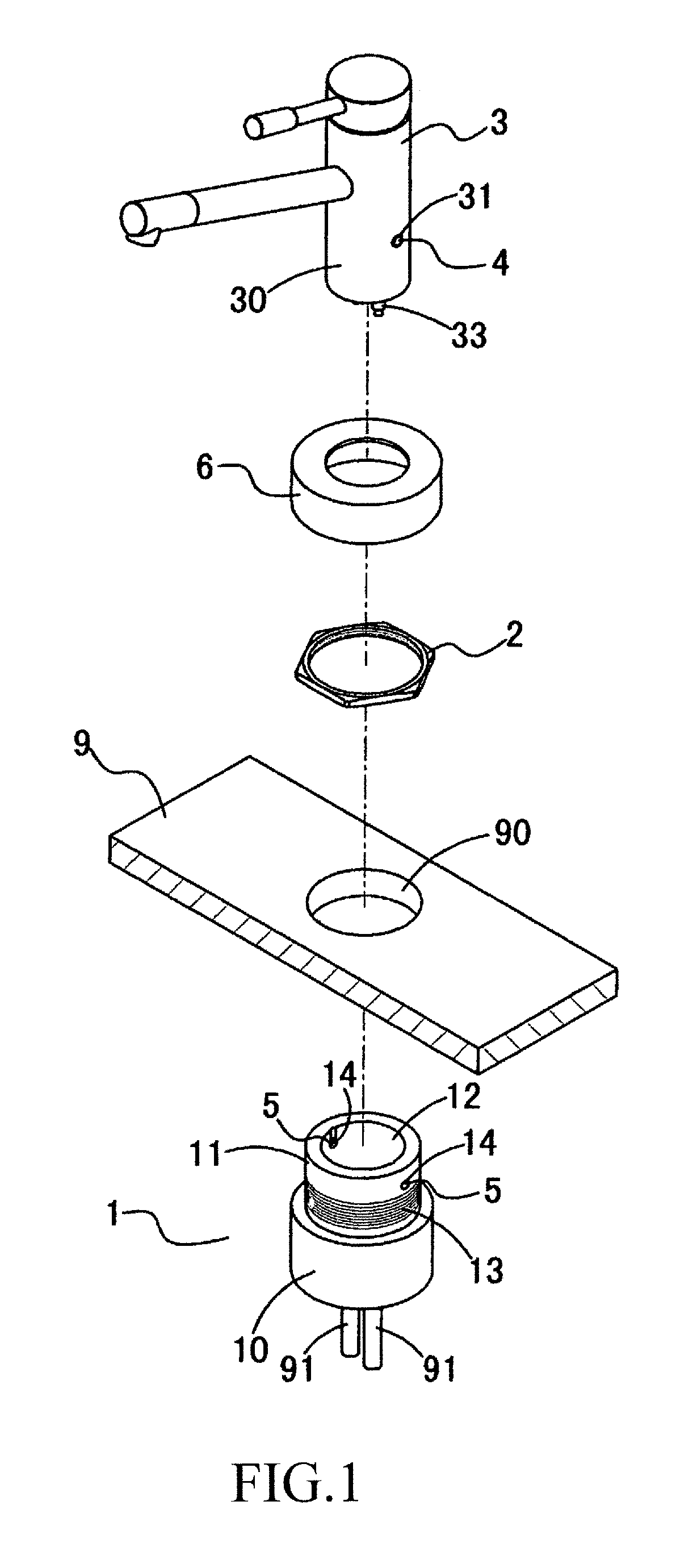
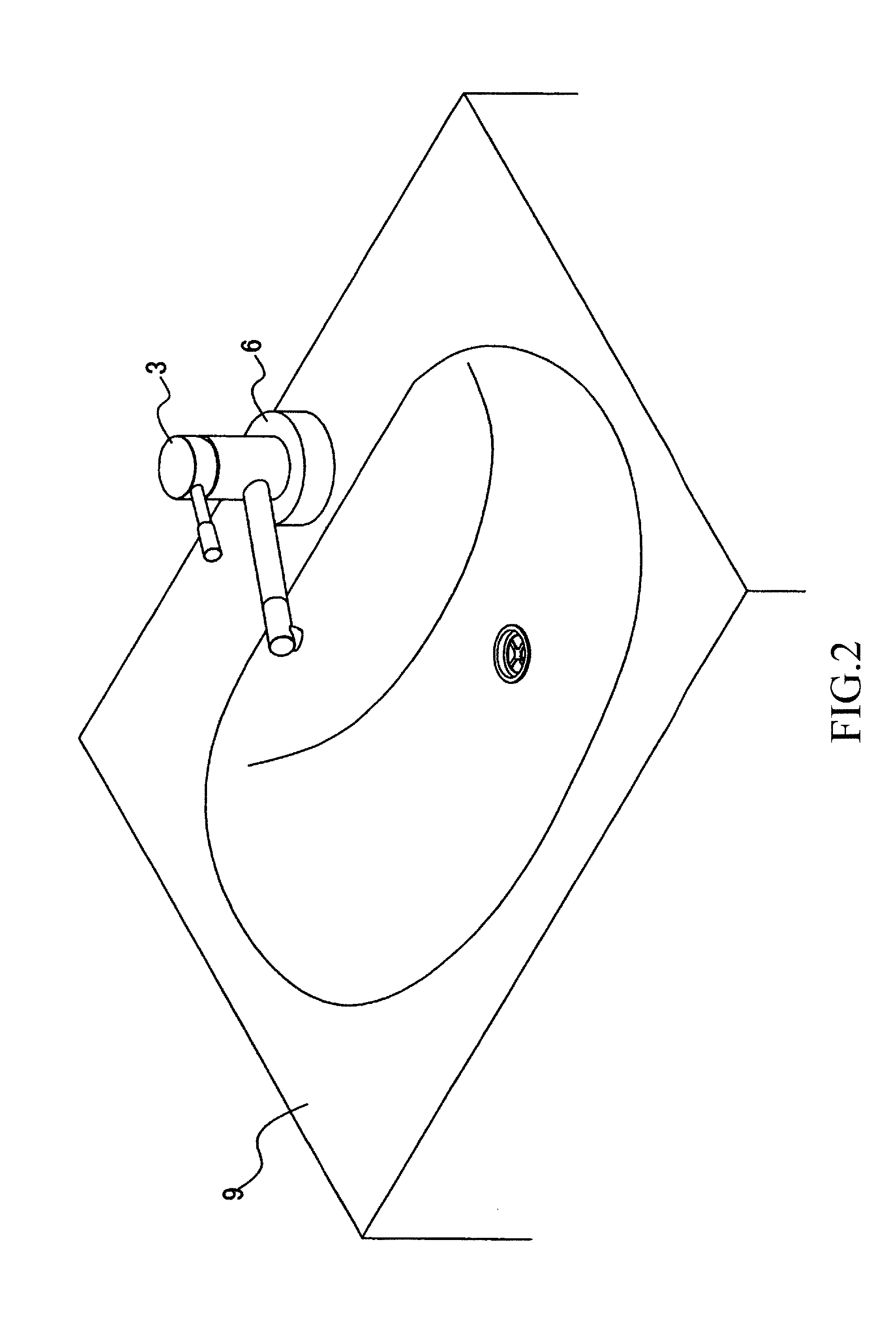
[0020]Referring to FIGS. 1, 2, and 5, the present invention provides an installation structure of countertop faucet, which comprises a base 1, a locking nut 2, a faucet 3, two positioning modules 4, two releasing modules 5, and a cover 6.

[0021]The base 1 comprises a seat 10 that is positionable against and thus abuts the underside of the top of a counter 9 of for example a sink or a wash basin and an insertion section 11 having a reduced diameter and extending through a mounting hole 90 of the count...


PUM


Abstract

An installation structure of countertop faucet includes a base having an insertion section extending through a mounting hole formed in a counter to engage a locking nut to be secured. The insertion section has a top end forming a receiving bore of which a circumferential wall forming two positioning holes communicating with the receiving bore. Each positioning hole receives therein a releasing module. The bottom of the base forms two water inlet passages communicating with the receiving bore and receiving stop valves therein and coupled to couplers for connection with water inlet tubes. A faucet has a joint section received in the receiving bore and having water guide tubes fit into the water inlet passages. The joint section forms two receiving apertures receiving therein positioning modules respectively engageable with the positioning holes to fix the faucet and being released by the releasing module to detach the faucet from the base.

Description

TECHNICAL FIELD OF THE INVENTION[0001]The present invention generally relates to the field of mounting / dismounting faucet, and more particularly to an installation structure enabling easy, efficient, and simple mounting and / or dismounting of a faucet on a countertop, including a lavatory countertop or a basin countertop.DESCRIPTION OF THE PRIOR ART[0002]In installing or replacing a faucet mounted on a basic countertop or a lavatory countertop, water pipes connected to the faucet must be closed first before dismounting / mounting operation can be carried out. After the installation, the water pipes must be opened again to inspect if any leak occurs.[0003]To install the countertop faucet, a lower end portion of the faucet must be first inserted into an installation hole that is previously formed in the countertop. A nut is then set into engagement with the lower end portion of the faucet from the underside of the countertop to secure the faucet on the countertop. After that, the water p...

Claims


Application Information

Patent Timeline
Patent Type & Authority Applications(United States)
IPC IPC(8): E03C1/04
CPCE03C1/0401E03C1/0403E03C2001/0416Y10T137/598
Inventor CHEN, MING-HUNGCHANG, CHIH-CHIANG
Owner CHEN MING HUNG
Learn More