Dual drive floor scrubber

a floor scrubber and dual drive technology, applied in the direction of carpet cleaners, cleaning equipment, manufacturing tools, etc., can solve the problems of difficult and fatiguing the operator, affecting the operation efficiency of the operator, etc., and achieve the effect of reducing the number of operators

Active Publication Date: 2013-11-07
DIVERSEY TASKI INC
View PDF10 Cites 19 Cited by
  • Summary
  • Abstract
  • Description
  • Claims
  • Application Information

AI Technical Summary

Problems solved by technology

Although these types of machines are utilized to maintain large floor areas, these vehicles need to be maneuverable while navigating in tight areas and around obstacles.
However, maneuvering the floor cleaning machine in this manner can be difficult and fatiguing for the operator.
This also can be difficult and fatiguing for the operator who typically needs to maneuver the floor cleaning machine into small tight areas.
The Mayer system is, however, limited by its drive control because the operator still has two machine controls, those being a steering member and a throttle to control the machine.
Also, the maneuverability of the machine is limited by pivoting around on a single axis by the wheels.

Method used


Image

  • Dual drive floor scrubber
  • Dual drive floor scrubber
  • Dual drive floor scrubber

Examples


Embodiment Construction

[0040]It is to be understood that the invention may assume various alternative orientations and step sequences, except where expressly specified to the contrary. It is also to be understood that the specific devices and processes illustrated in the attached drawings, and described in the following specification are simply exemplary embodiments of the inventive concepts. Hence, specific dimensions, directions or other physical characteristics relating to the embodiments disclosed are not to be considered as limiting, unless expressly stated otherwise.

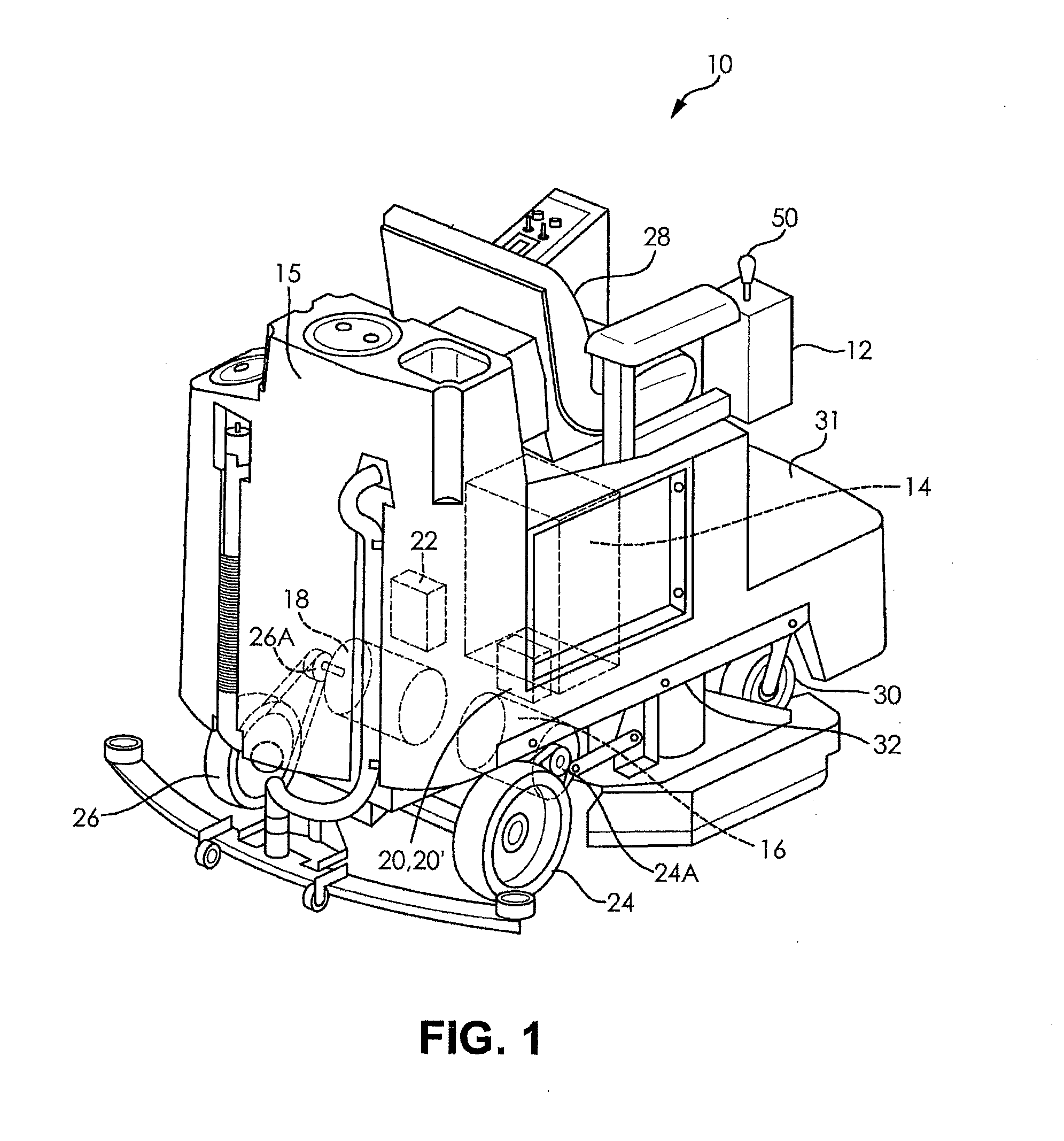
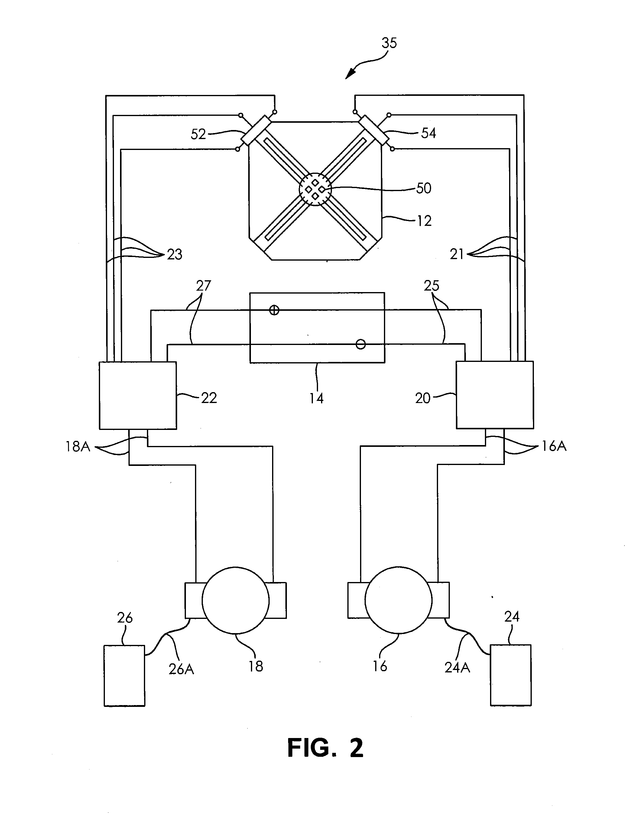
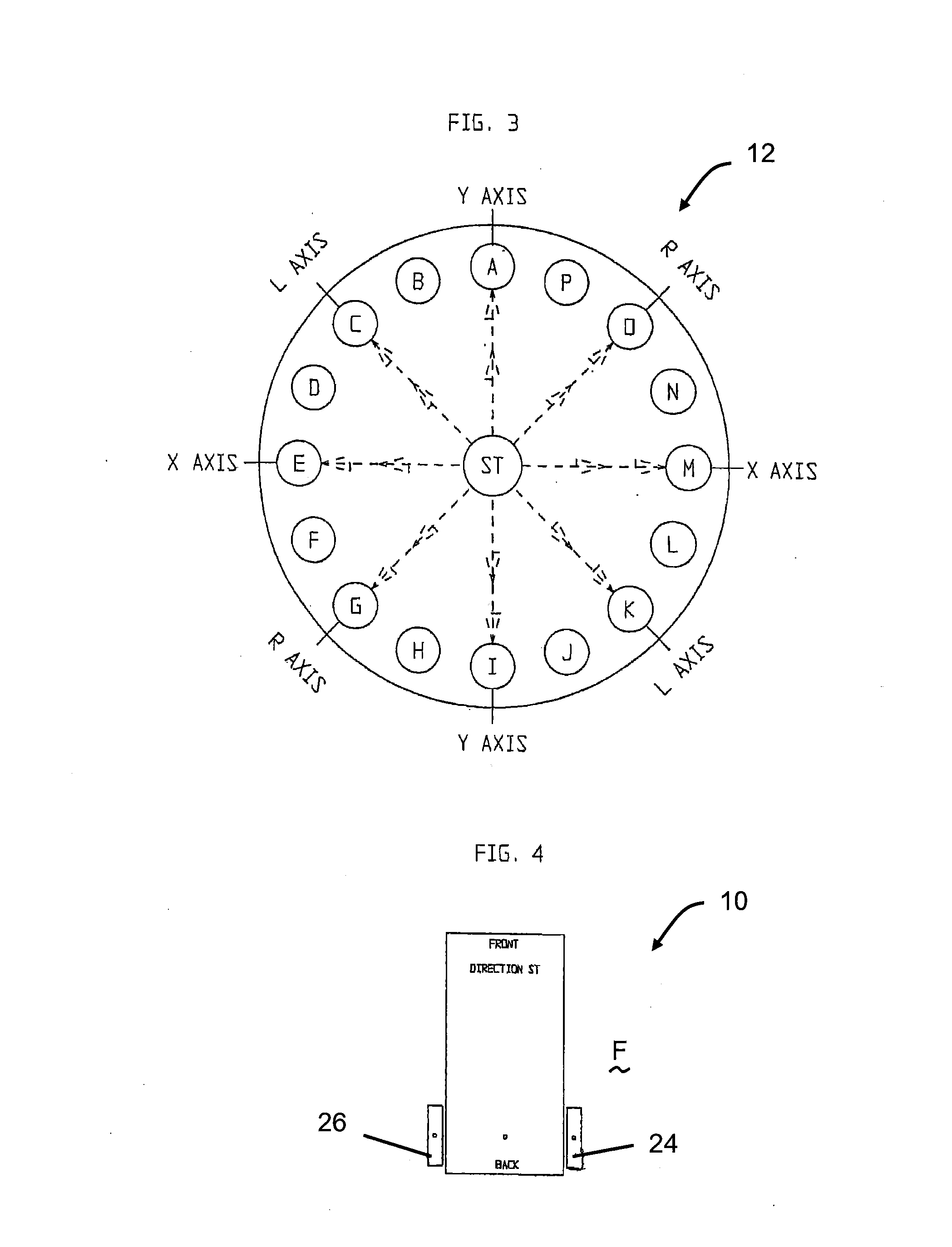
[0041]FIG. 1 illustrates a ride-on floor cleaning / burnishing machine 10 having an analog joystick control 12, an electric power source 14, at least one cleaning tank 15, right and left electrical drive motors 16, 18, right and left motor controller portions 20, 22 or a single motor controller 20′ that controls both right and left motors, and right and left rear steering drive wheels 24, 26. The ride-on floor cleaning / burnishing machine 1...


PUM


Abstract

A floor cleaning or burnishing machine has at least one motor controller that is electrically connected to an analog joystick control, right and left potentiometers, an electrical power source, and right and left electrical drive motors. The right motor is mechanically connected to a right rear steering drive wheel and the left motor is mechanically connected to a left rear steering drive wheel. Rotational speed and direction of each rear wheel is independently controlled, by way of the joystick in cooperation with respective potentiometers, in either a forward or reverse direction. At any given time, each potentiometer controls a respective motor controller which individually controls the rotational speed and direction of a respective wheel, thereby each wheel is capable of rotating in an opposite direction at a different speed to the other wheel. To slow the floor cleaning or burnishing machine down, regenerative braking is utilized by operating the motors as generators.

Description

RELATED APPLICATION[0001]This application claims the benefit under 35 U.S.C. §119(e) of U.S. Provisional Patent Application Ser. No. 61 / 641,932, filed May 3, 2012, which is incorporated by reference herein in its entirety.FIELD OF THE INVENTION[0002]The present invention relates to a floor cleaning or burnishing machine and, more particularly, to precise control of a floor cleaning or burnishing machine with a joystick.BACKGROUND OF THE INVENTION[0003]Currently, floor cleaning machines and, in particular, battery powered automatic floor cleaning machines are either walk behind or ride-on type of machines. Floor cleaning machines have many functions including vacuuming, sweeping, buffing, stripping, scrubbing and carpet cleaning. Generally, battery powered automatic floor cleaning machines that are applied in the floor care industry are typically utilized to maintain flooring in large areas.[0004]Although these types of machines are utilized to maintain large floor areas, these vehic...

Claims


Application Information

Patent Timeline
Patent Type & Authority Applications(United States)
IPC IPC(8): A47L11/28A47L11/40
CPCA47L11/28A47L11/4005A47L11/4061A47L11/4066B62D11/003
Inventor FELLHAUER, JEFFERY R.BRASHEAR, JR., WILLIAM E.KRAUSNICK, DALE A.
Owner DIVERSEY TASKI INC
Why Eureka
Try Eureka