
Cut-sheet feeder

a feeder and sheet metal technology, applied in the direction of registering devices, thin material processing, article separation, etc., to achieve the effect of smooth handover, and reducing the occurrence of partial double feeding

Inactive Publication Date: 2013-11-07
EZAWA JIMUKI
View PDF10 Cites 3 Cited by
  • Summary
  • Abstract
  • Description
  • Claims
  • Application Information

AI Technical Summary

Benefits of technology

The invention is a cut-sheet feeder that includes a belt contact amount adjuster to prevent partial double feeding (when a cut sheet partially overlaps with the one below it) during the cutting process. The adjuster can be positioned to vary the contact area between the feed belt and the stack of cut sheets. The feeder also includes an inclined guide member that helps spread the lower end portions of the cut sheet to prevent partial double feeding. The position of the belt contact amount adjuster and the inclined guide member can be adjusted separately to accommodate changes in the size of the cut sheets. The feeder also includes a hand-over projection to prevent the cut sheet from being folded, and a cover section to support the cut sheet. The belt contact amount adjuster can be fixed at a given position along a guide or using a magnet and clamp. The belt contact amount adjuster can be linearly moved or stabilized in the direction of feeding of cut sheets. The invention helps improve the stability and efficiency of the cut-sheet feeding process.

Problems solved by technology

However, the aforementioned conventional cut-sheet feeder would tend to cause a problem, so-called “partial double feeding” that the rear end portion of one cut sheet drawn in ahead from a stack of cut sheets overlapped the front end portion of the subsequent cut sheet when being fed.

Method used


Image

  • Cut-sheet feeder
  • Cut-sheet feeder
  • Cut-sheet feeder

Examples


first embodiment

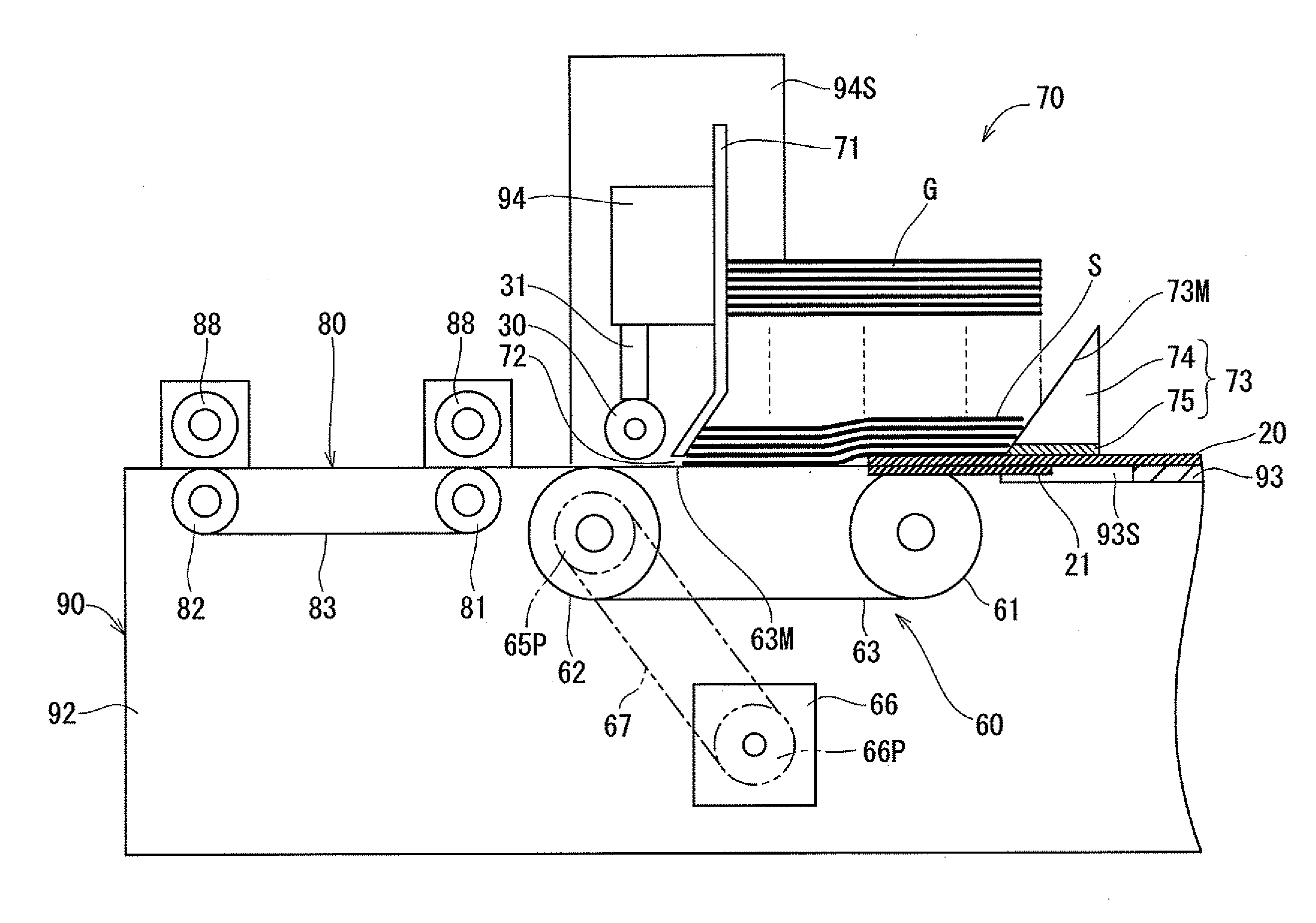
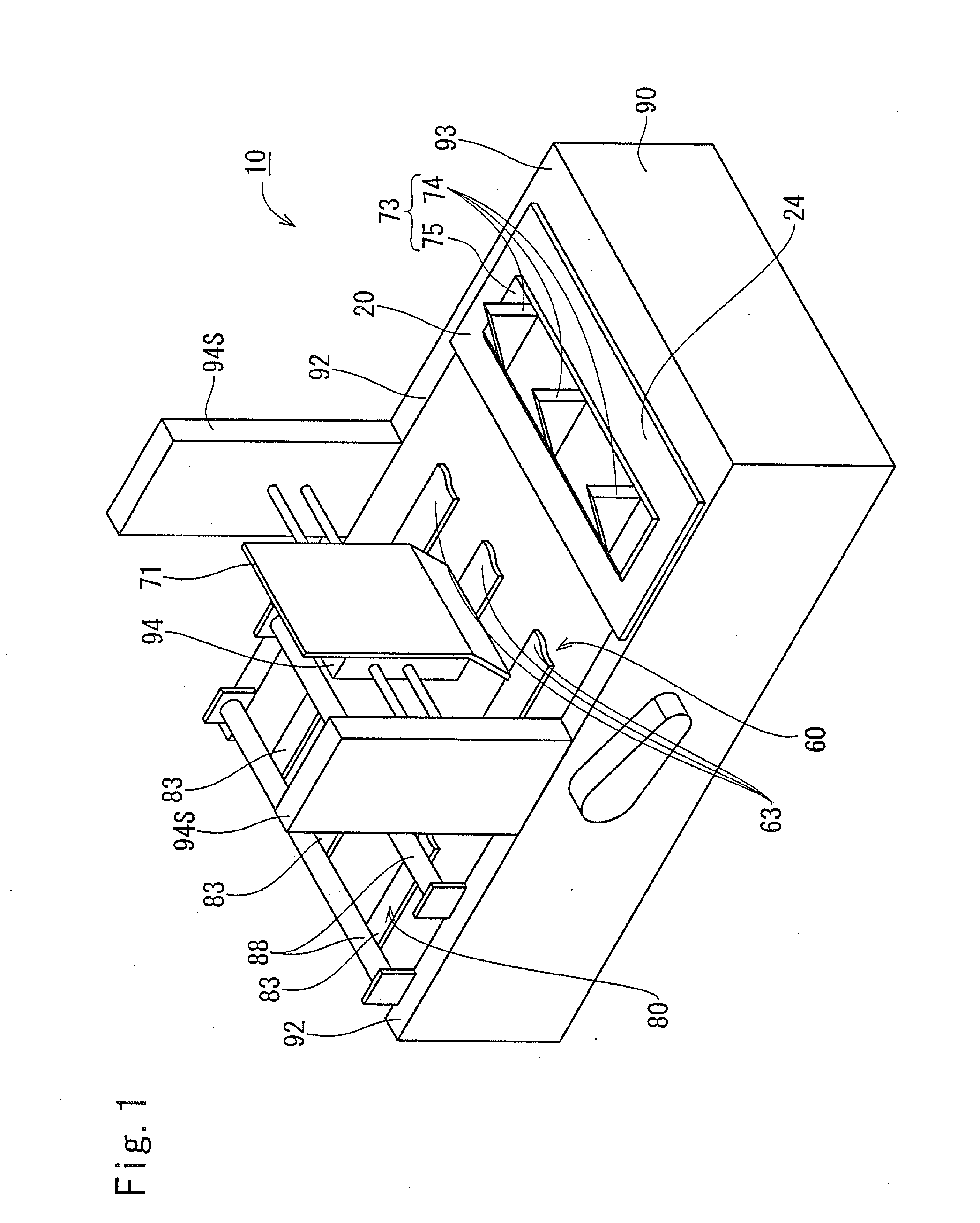
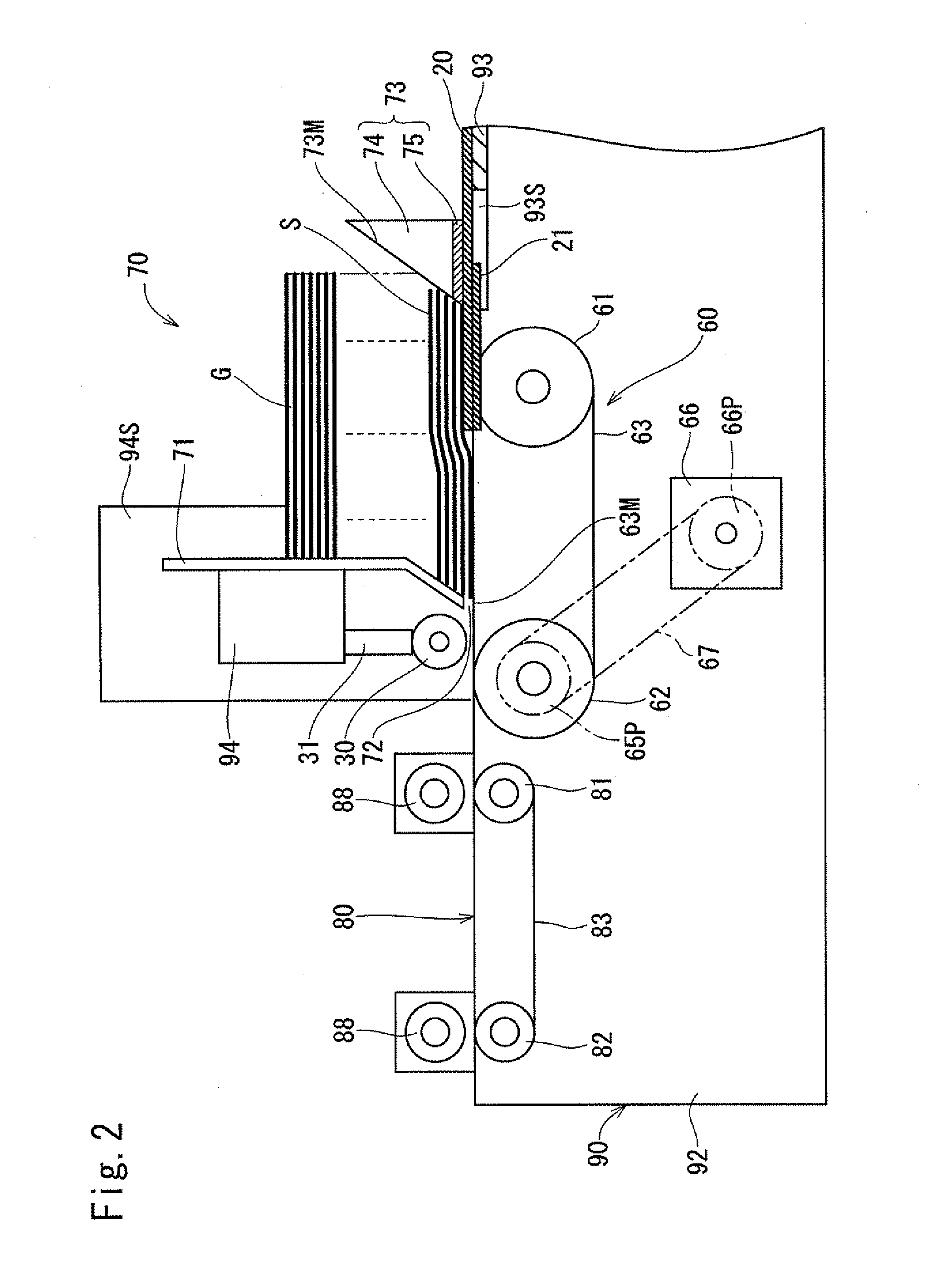
[0055]Hereinafter, a description will be made of a first embodiment of the present invention with reference to FIGS. 1 to 6. As shown in FIG. 1, a cut-sheet feeder 10 according to the present invention has various types of parts disposed on a base frame 90. The base frame 90, which is formed as a whole in the shape of a box, includes side plates 92 and 92 opposed to each other in the horizontal direction and an upper surface plate 93 for coupling between the rear end portions of the side plates 92. Note that the upper surface plate 93 is in parallel to the horizontal plane.

[0056]At the substantial center of the side plates 92 and 92 in the back-and-forth direction, side walls 94S and 94S stand upright. At a position sandwiched between those side walls 94S and 94S, there is provided a parts mounting unit 94. Provided behind the parts mounting unit 94 is a stock unit 70 in which a stack of cut sheets G can be placed with a plurality of cut sheets S stacked on top of another in the up-...

second embodiment

[0084]Hereinafter, a description will be made of a second embodiment of the present invention with reference to FIGS. 7 to 9. As shown in FIG. 7, a cut-sheet feeder 10V according to this embodiment features that the configuration of a belt contact amount adjuster 20V is mainly different from the configuration of the belt contact amount adjuster 20 of the first embodiment.

[0085]The belt contact amount adjuster 20V has a cover section 24 with an upper surface parallel to a horizontal plane, and the cover section 24 covers the range of the rotational contact surface 63M of the feed belts 63 from the rear end to an intermediate position thereof. Note that, more specifically, the cover section 24 is horizontal plate-shaped and aligned so as to be sandwiched between an upper surface plate 93 and the mounting plate 75 of the inclined guide member 73.

[0086]As shown in FIG. 8, the cover section 24 has the first elongated guide hole 20A which is formed to penetrate therethrough in the same ma...

third embodiment

[0092]Hereinafter, a description will be made of a third embodiment of the present invention with reference to FIGS. 10 to 13. As shown in FIG. 10, a cut-sheet feeder 10W of this embodiment features that the configuration of a belt contact amount adjuster 20W is mainly different from that of the belt contact amount adjuster 20V of the second embodiment. More specifically, the belt contact amount adjuster 20W has a flat surface, the upper surface of the entirety of which is inclined forwardly downward.

[0093]As shown in FIGS. 10 and 11, the belt contact amount adjuster 20W includes a plurality of hand-over projections 25W disposed between adjacent feed belts 63 and 63 and a cover section 24W in communication with the rear ends of the plurality of hand-over projections 25W. The cover section 24W is provided at the rear end portion with a plurality of slits 24WS so as to allow the triangular plates 74W of inclined guide members 73W to be movable in the back-and-forth direction in the sl...


PUM


Abstract

A cut-sheet feeder has a feed belt, a belt contact amount adjuster, and an inclined guide member. The belt makes contact with the lowermost cut sheet of a stack of cut sheets and feeds forward the cut sheet. The belt contact amount adjuster supports the stack of cut sheets while lifting the read portion thereof from the feed belt. The inclined guide member protrudes further upward than the belt contact amount adjuster and has a guide surface inclined forwardly downward. The guide surface lifts up the rear end portion of the stack of cut sheets and shifts forward the lowermost cut sheet. The position of the adjuster in the front-rear direction and the position of the guide member in the front-rear direction can be adjusted individually.

Description

TECHNICAL FIELD [0001]The present invention relates to a cut-sheet feeder which sequentially draws and feeds a cut sheet from a stack of cut sheets with one placed on another.Background Art[0002]Conventionally known as a cut-sheet feeder of this type is one which brings a feed belt into rotational contact with the lower end of a stack of cut sheets while the rear end portion of the stack of cut sheets is being lifted up by an inclined guide member having a frontward inclined upper surface (e.g., Patent Document 1).PRIOR ART DOCUMENT Patent Document[0003]Patent Document 1: Japanese Published Unexamined Patent Application No. 2010-168201 (FIG. 1)SUMMARY OF THE INVENTIONProblem to be Overcome by the Invention[0004]However, the aforementioned conventional cut-sheet feeder would tend to cause a problem, so-called “partial double feeding” that the rear end portion of one cut sheet drawn in ahead from a stack of cut sheets overlapped the front end portion of the subsequent cut sheet when b...

Claims


Application Information

Patent Timeline
IPC IPC(8): B65H3/04
CPCB65H3/042B65H1/06B65H3/54B65H3/68B65H9/101B65H2405/11152B65H2405/1122B65H2405/1124B65H3/04B65H3/56
Inventor ITO, YUHIKO
Owner EZAWA JIMUKI
Learn More