

Contact lens for myopia control
a technology of contact lenses and myopia, which is applied in the field of contact lenses, can solve the problems of wearer discomfort and temptation to wear contact lenses, and achieve the effect of relieving wearer of any discomfort in wearing contact lenses and suppressing the progression of myopia
- Summary
- Abstract
- Description
- Claims
- Application Information
AI Technical Summary
Benefits of technology
Problems solved by technology
Method used
Image


Examples
Embodiment Construction
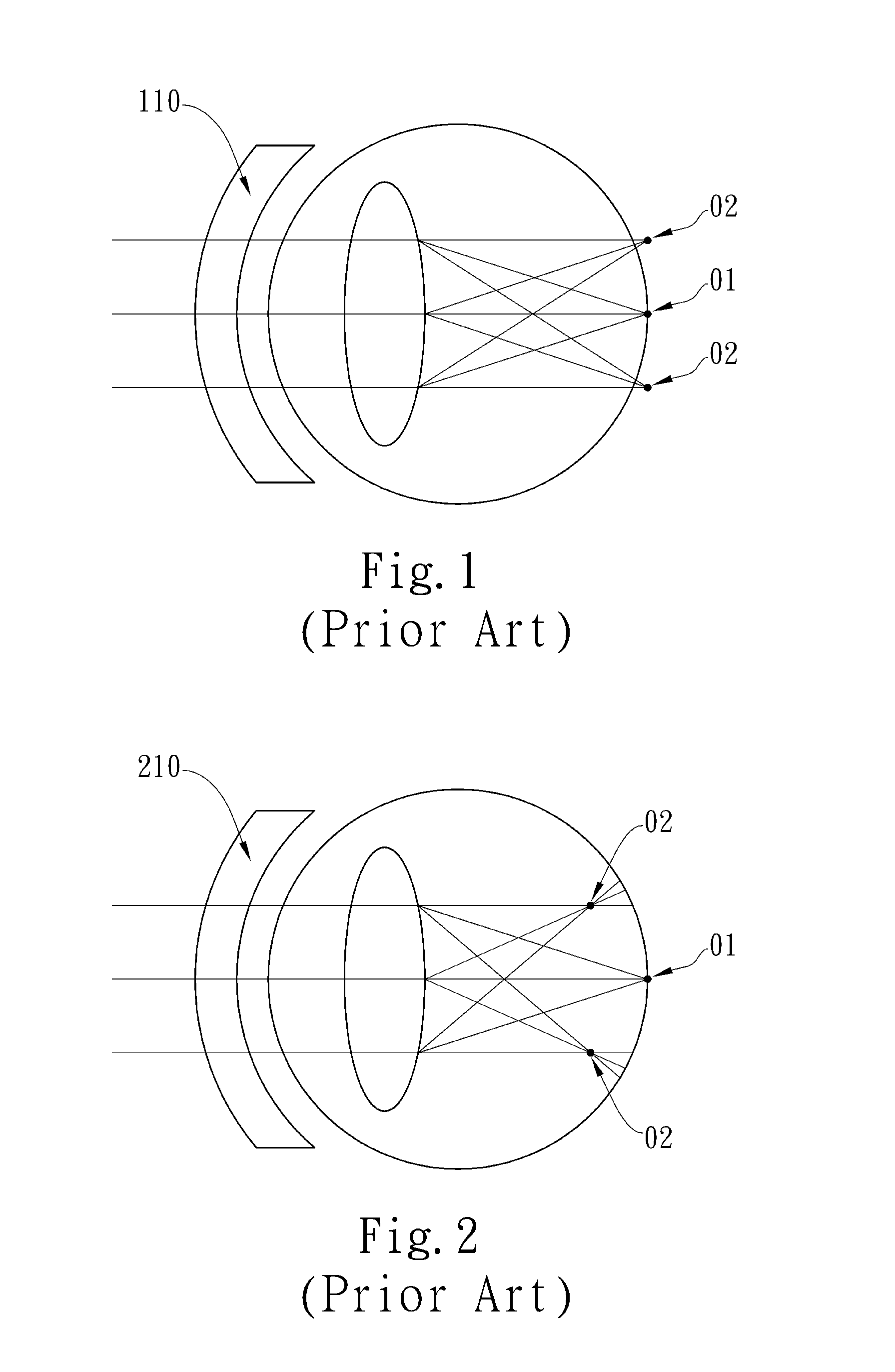
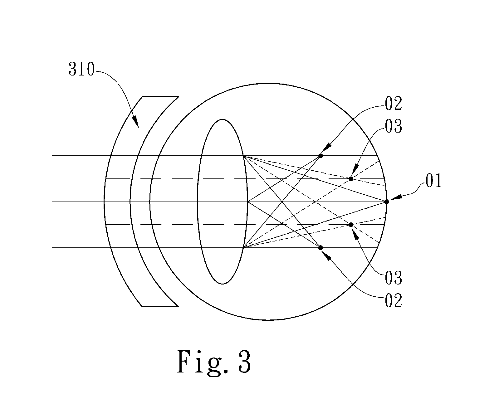
[0014]The term “central zone” of the present invention refers to a region of the contact lens configured to correct the central vision; the term “peripheral zone” refers to a region of the contact lens configured to correct the peripheral vision; the term “transition zone” refers to a region of the contact lens configured to connect “central zone” and “peripheral zone”. In the present invention, the term “fovea” refers to a region located in the center of the retina and responsible for central vision; the term “para-fovea” refers to a region located outside the fovea and responsible for the peripheral vision. While the reference numerals 01, 02 and 03 in the appended drawings illustrate the relative relation among the focuses of respective zones, each zone of the contact lens is not limited to have only one focus.
[0015]FIG. 4 is a schematic representation of the contact lens 310 for myopia control in accordance with the present invention, wherein FIG. 4A is a schematic representatio...
PUM
 Abstract
Description
Claims
Application Information