Multi-Cell Incremental Redundancy

a wireless communication access network and incremental redundancy technology, applied in the direction of site diversity, wireless commuication services, transmitter monitoring, etc., can solve the problem of largely limited user performan

Active Publication Date: 2013-11-07
AVAGO TECH INT SALES PTE LTD
View PDF13 Cites 23 Cited by
  • Summary
  • Abstract
  • Description
  • Claims
  • Application Information

AI Technical Summary

Problems solved by technology

In wireless communication access networks, such as cellular networks for example, user performance is largely limited by interference from neighboring cells.

Method used


Image

  • Multi-Cell Incremental Redundancy
  • Multi-Cell Incremental Redundancy
  • Multi-Cell Incremental Redundancy

Examples


Embodiment Construction

[0016]For purposes of this discussion, the term “module” shall he understood to include at least one of software, firmware, and hardware (such as one or more circuits, microchips, or devices, or any combination thereof), and any combination thereof. In addition, it will be understood that each module can include one, or more than one, component within an actual device, and each component that forms a part of the described module can function either cooperatively or independently of any other component forming a part of the module. Conversely, multiple modules described herein can represent a single component within an actual device. Further, components within a module can be in a single device or distributed among multiple devices in a wired or wireless manner.

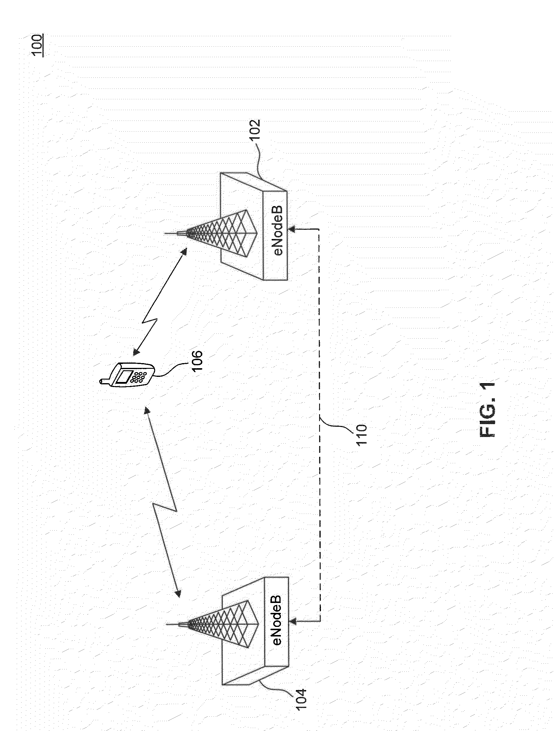
[0017]In the following disclosure, terms defined by the Long-Term Evolution (LTE) standard are sometimes used. For example, the term “eNodeB” is used to refer to what is commonly described as base station (BS) or base transcei...


PUM


Abstract

Embodiments enable cooperative transmissions from a group of cells (can include the serving cell and one or more neighboring cells) to a user equipment (UE). The cooperative transmissions emulate Hybrid Automatic Repeat Request (HARQ) transmissions to the UE. Specifically, when the UE is experiencing high interference, the UE's serving cell can create a transmit incremental redundancy (IR) group for the UE, which is used to transmit information in a HARQ-like fashion to the UE. Because interference is reduced, the UE can decode the information at a lower coding rate and higher coding gain.

Description

CROSS-REFERENCE TO RELATED APPLICATIONS[0001]The present invention claims the benefit of U.S. Provisional Application No. 61 / 642,967, filed May 4, 2012, which is incorporated herein by reference in its entirety.BACKGROUND [0002]1. Field of the Invention[0003]The present disclosure relates generally to multi-cell incremental redundancy schemes for wireless communication access networks.[0004]2. Background Art[0005]In wireless communication access networks, such as cellular networks for example, user performance is largely limited by interference from neighboring cells. For example, in a single frequency network (SFN), about 30% of the users have a Carrier-to-Interference and Noise Ratio (CINR) of 0 dB or below. Interference is particularly a concern for users that happen to be located at radio cell edges (cell edge users) due to proximity to neighboring cells.BRIEF DESCRIPTION OF THE DRAWINGS / FIGURES[0006]The accompanying drawings, which are incorporated herein and form a part of the...

Claims


Application Information

Patent Timeline
Patent Type & Authority Applications(United States)
IPC IPC(8): H04W72/08
CPCH04W72/082H04B7/024H04B17/16H04L1/0077H04L1/1819H04L1/1874H04W72/541
Inventor JALLOUL, LOUAYTUJKOVIC, DJORDJEMOHAMMED, AHMAD
Owner AVAGO TECH INT SALES PTE LTD
Why Eureka
Try Eureka