Decomposition of 3D geometry into developable surface patches and 2d cut patterns

Active Publication Date: 2013-11-07
AUTODESK INC
View PDF7 Cites 30 Cited by
  • Summary
  • Abstract
  • Description
  • Claims
  • Application Information

AI Technical Summary

Benefits of technology

[0007]One embodiment sets forth a method for decomposing three-dimensional (3D) geometry into developable surface patches. The method includes receiving the 3D geometry growing surface patches from faces in the 3D geometry. Growing the surface patches may include performing the following steps until stabilization criteria are met: (1) selecting one or more seed faces, from the faces in the 3D geometry, as initializations of the surface patches; and (2) up to a distance threshold, iteratively ad

Problems solved by technology

However, each part, once cut to shape, can only be (approximately) isometrically deformed, as the proper

Method used


Image

  • Decomposition of 3D geometry into developable surface patches and 2d cut patterns
  • Decomposition of 3D geometry into developable surface patches and 2d cut patterns
  • Decomposition of 3D geometry into developable surface patches and 2d cut patterns

Examples


Embodiment Construction

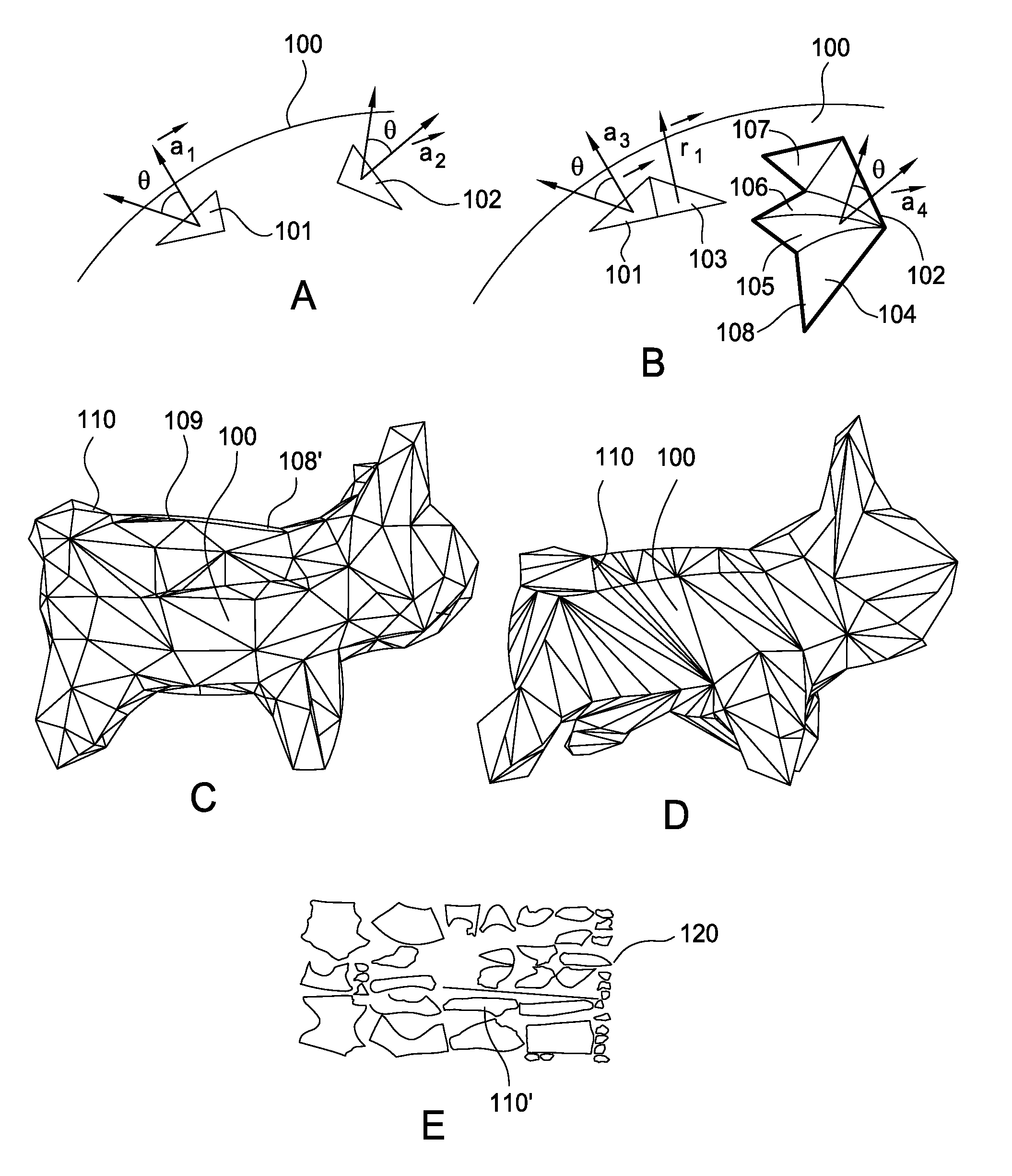
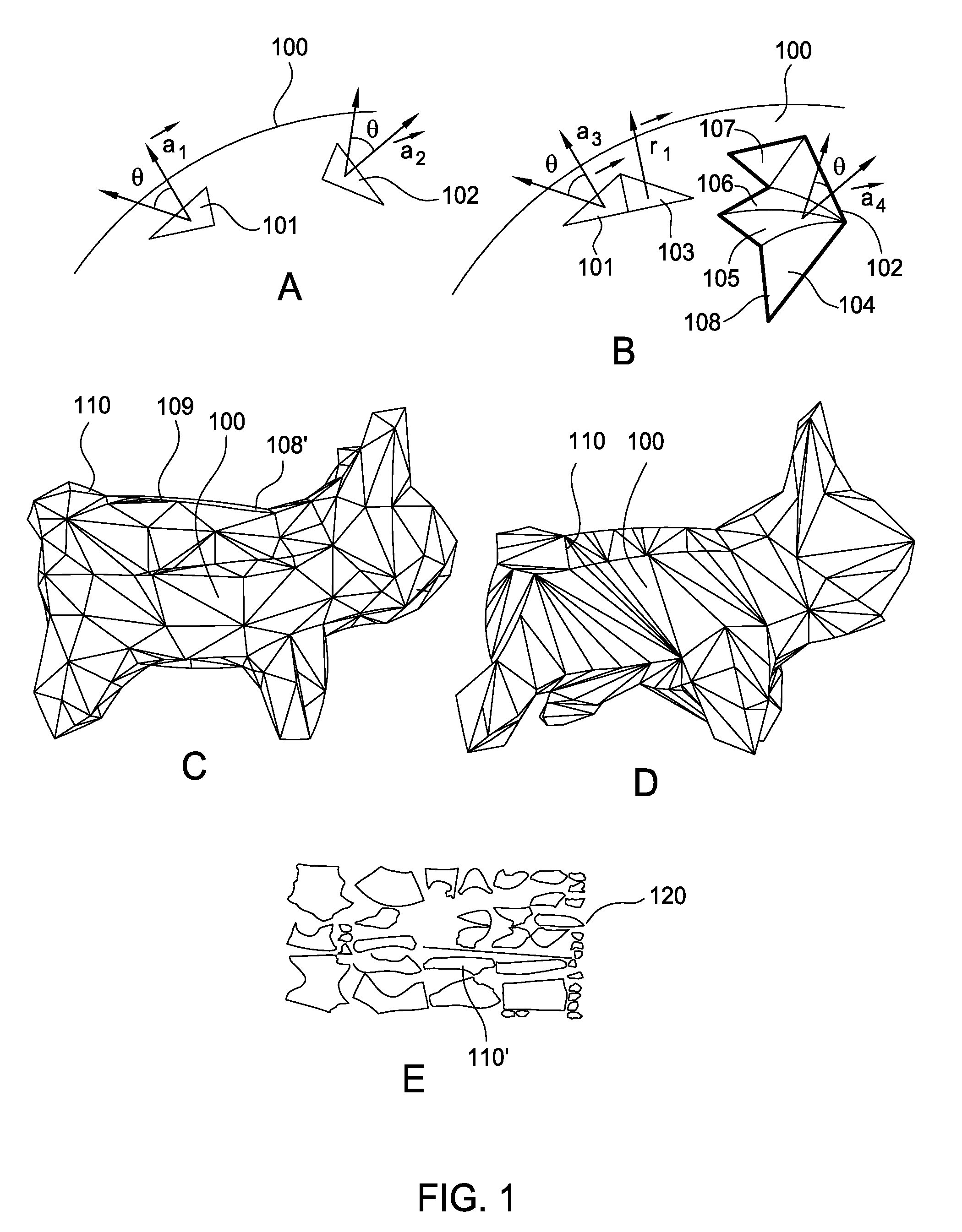
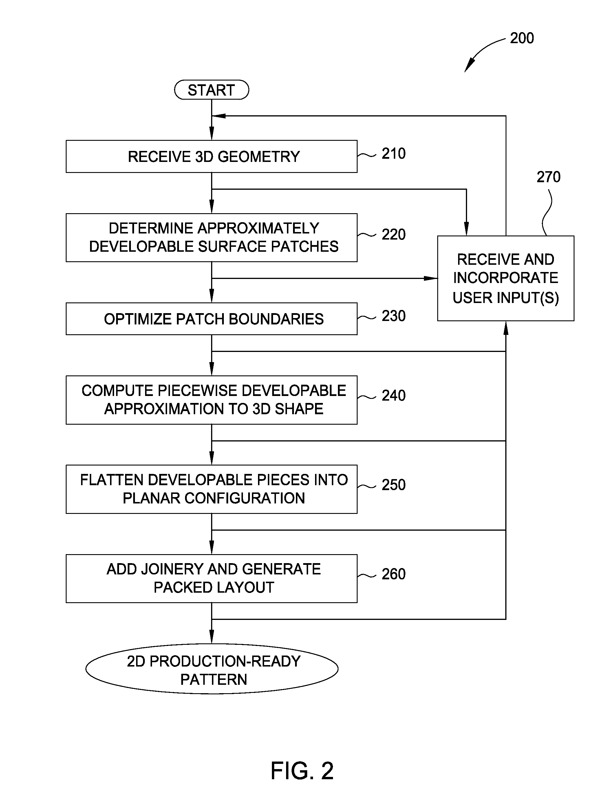
[0017]Embodiments disclosed herein provide techniques for decomposing 3D geometry into developable surface patches and cut patterns. In one embodiment, a decomposition application receives a triangulated 3D surface as input and determines approximately developable surface patches from the 3D surface using a variant of k-means clustering. Beginning with seed triangles, patches are iteratively grown by adding the face with minimum distance to any patch to that patch which has the minimum distance to the face, until no face is less than a threshold distance from its closest patch. As used herein, a face is a closed set of edges, such as a triangle. The decomposition application may also merge adjacent patches. Then, if significant surface area is not assigned to any patch, the decomposition application chooses new seeds that are as far from the current patches' boundaries as possible, and iteratively grows new patches from the new seeds.

[0018]Approximately developable surface patches m...


PUM


Abstract

Embodiments disclosed herein provide techniques for decomposing 3D geometry into developable surface patches and cut patterns. In one embodiment, a decomposition application receives a triangulated 3D surface as input and determines approximately developable surface patches from the 3D surface using a variant of k-means clustering. Such approximately developable surface patches may have undesirable jagged boundaries, which the decomposition application may eliminate by generating a data structure separate from the mesh that contains patch boundaries and optimizing the patch boundaries or, alternatively, remeshing the mesh such that patch boundaries fall on mesh edges. The decomposition application may then flatten the patches into truly developable surfaces by re-triangulating the patches as ruled surfaces. The decomposition application may further flatten the ruled surfaces into 2D shapes and lay those shapes out on virtual sheets of material. A person, or machinery, may cut out those shapes from physical sheets of material based on the layout.

Description

CROSS-REFERENCE TO RELATED APPLICATION[0001]This application claims benefit of U.S. Provisional Patent Application Ser. No. 61 / 621,940 filed Apr. 9, 2012, which is incorporated herein by reference in its entirety.BACKGROUND OF THE INVENTION[0002]1. Field of the Invention[0003]The present invention generally relates to computer software. More specifically, the present invention relates to techniques for decomposing three-dimensional (3D) geometry into developable surface patches and two-dimensional (2D) cut patterns.[0004]2. Description of the Related Art[0005]A number of sheet materials used to manufacture objects strongly resist stretching and shearing, but not bending. Such materials include sheet metal, textiles, and sheets of wood, each of which is typically easy to mass-produce and cut into shapes using, e.g., stamping, water jet, or laser cutters. Use of such materials may be cost-effective and preferable to more expensive molded or machined parts. However, each part, once cut...

Claims


Application Information

Patent Timeline
IPC IPC(8): G06F17/50
CPCG06F17/50G06F30/00G06F2113/24
Inventor GRIFFITH, SAULWICKE, MARTINPASKO, KEITHIRVING, GEOFFREYCALISCH, SAMGILMAN, TUCKERBENOIT, DANIELBACHRACH, JONATHAN
Owner AUTODESK INC
Why Eureka
Try Eureka