Sensor arrangement, for example, on an anchor bolt

Active Publication Date: 2013-11-14
HILTI AG
View PDF3 Cites 6 Cited by
  • Summary
  • Abstract
  • Description
  • Claims
  • Application Information

AI Technical Summary

Benefits of technology

[0007]The present invention provides for at least one bypass element that at least partially dissipates the impact forces that occur during the hammering step, thus relieving the pressure on the sensor and protecting it. The bypass element here has a dilatant material, at least in certain areas, by means of which the impact forces are dissipated. Such a dilatant material is characterized in that it resists deformation if a force is applied over a short period of time, for instance, less than 0.1 seconds, and yet it is deformable if the force is applied for a longer period of time of, for example, more than 3 seconds. In this manner, the dilatant material can absorb forces of short duration such as those that occur due to hammer strikes, and can cause them to bypass the sensor, thus p

Problems solved by technology

However, it has been found that, at times, direct tension indicators do not function reliably when they are employed in concrete anchors.
These impact forces can damage or at least weaken the dye-fil

Method used


Image

  • Sensor arrangement, for example, on an anchor bolt
  • Sensor arrangement, for example, on an anchor bolt

Examples


Embodiment Construction

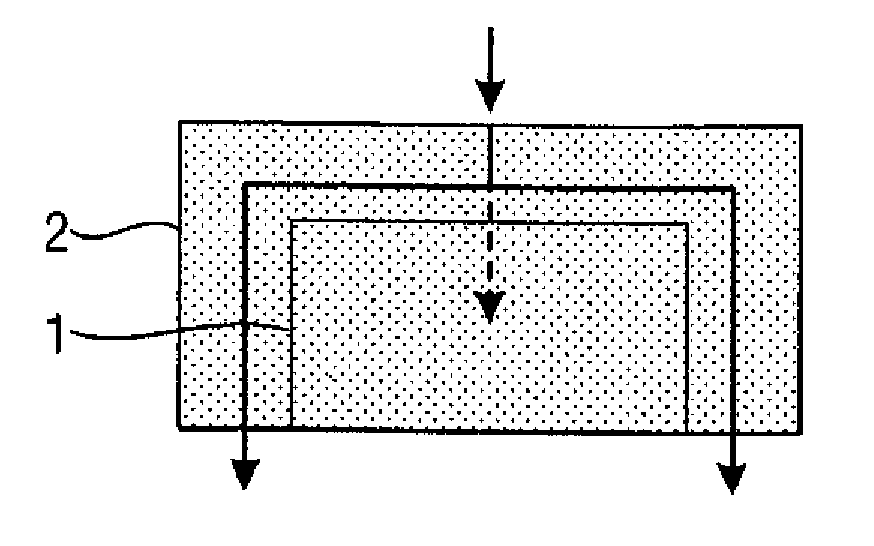
[0016]FIG. 1 shows a first embodiment of a sensor arrangement according to the invention. The arrangement shows a sensor 1 that can be configured, for instance, mechanically or even electrically. Moreover, the arrangement has a bypass element 2 that is made of a dilatant material. The sensor 1 is embedded into this material, whereby the dilatant material runs on the top of the sensor I as well as along its two sides. If an impact is now applied from the top onto the sensor arrangement of FIG. 1, the appertaining force, as shown by solid arrows in FIG. 1, is absorbed by the dilatant material of the bypass element 2 and dissipated on both sides of the sensor 1. The sensor 1, in contrast, is only loaded slightly or not at all.

[0017]If, on the other hand, the force acts from the top for a longer period of time, then the dilatant material can be deformed and the force acting from the top, as shown with a broken-line arrow in FIG. 1, can act upon the sensor 1 and can be detected by it. Th...


PUM


Abstract

A sensor arrangement, for example, on an anchor bolt, including at least one sensor (10). At least one bypass element (20) with a dilatant material is arranged in the area of the sensor (10), whereby impact forces that act upon the sensor (10) can be dissipated via the dilatant material of the bypass element (20).

Description

[0001]The invention relates to a sensor arrangement, for example, on an anchor bolt.BACKGROUND[0002]German patent specification DE 103 16 632 B4, for instance, discloses a screw bolt having a so-called load-indicator disk, also referred to as a “direct tension indicator” (DTI). Such an indicator has sensors for checking the tension set on the screw bolt, whereby the sensors consist of capsules that are filled with a dye. At a predefined axial load, the dye comes out of the indicator and / or becomes visible at the edge of the indicator. Therefore, the sensors can confirm that the target tension has been reached without the need to detect the installation torque.SUMMARY OF THE INVENTION[0003]However, it has been found that, at times, direct tension indicators do not function reliably when they are employed in concrete anchors.[0004]It is an object of the present invention to provide a particularly reliable sensor arrangement.[0005]The present invention provides that at least one bypass...

Claims


Application Information

Patent Timeline
IPC IPC(8): G01N3/22
CPCG01N3/22F16B13/065F16B31/028F16B2031/022
Inventor ECKSTEIN, ANDREASGOLDT, MATHIASSCHAEFFER, MARCAPPL, JOURGDIJKHUIS, ARJEN DETMERPAETOW, MATTHIAS
Owner HILTI AG
Why Eureka
Try Eureka